| Home | Energy Physics | Nuclear Power | Electricity | Climate Change | Lighting Control | Contacts | Links |
|---|
REACTOR DESIGN GOAL:
The purpose of the Fast Neutron Reactor (FNR) design outlined on this web site is to solve the global warming problem. This FNR is not intended to meet any particular performance or cost goals relating to a particular electricity market. Instead the priority is to develop a FNR that can be widely deployed and that can sustainably displace almost all fossil fuels.
Global warming is a result of too much combustion of fossil fuels. Any solution to global warming requires a sustainable nuclear fuel cycle. This fuel sustainability requirement can only be met by use of an abundant nuclear fuel. In this respect the only nuclear fuels with sufficient natural abundance are U-238, Th-232, Li-6 and H-2. Of these four fuels, due to unresolved technical challenges, only U-238 can be sustainably deployed in the near term.
Realizing nuclear fuel sustainability requires some degree of used nuclear fuel reprocessing. This subject must be approached in a rational manner, not from the perspective of irrational fear of nuclear weapon proliferation. For the fuel cycle described herein the fuel's Pu-240 / Pu-239 ratio is too large for making fission bombs.
A complicating issue relating to fossil fuel displacement is that much of mankind lives in energy poverty. For impoverished people the near term benefits of additional fossil fuel consumption outweigh the longer term problems related to an increased atmospheric CO2 concentration. Hence any practical solution to global warming must provide at least twice as much clean energy as is required to both displace the present fossil fuel consumption and to raise the amount of energy available to impoverished people to about half that in the developed world. There is not enough natural fissile fuel to meet projected near term human requirements. Hence the importance of adoption of a sustainable nuclear fuel cycle is paramount.
If nuclear power is to supply much of mankind's future energy the issue of nuclear waste must be faced. Almost all the nuclear waste isotopes from the contemplated fast neutron fuel cycle have relatively short half lives, so that most of the processed nuclear waste naturally decays to a stable state within a few centuries.
Since global warming is a world wide problem the reactors must be constructed out of materials that are plentiful and are widely available around the world.
In the circumpolar countries one of the largest present uses of fossil fuels is for comfort heating. Economic supply of the required comfort heat requires nuclear reactors that can be urban sited to directly supply district heat as well as electricity. The urban siting requirement indirectly dictates a range of reactor features related to reactor assembly, operation, maintenance and safety.
The maximum capacity of an urban sited reactor is constrained by practical heat removal constraints.
Urban reactor siting also constrains the reactor technology used because in a city there is no room for a public safety exclusion zone around the reactor.
The issue of public safety also means that the reactor must be designed to safely resist any credible untoward event.
Urban sited reactors must be capable of fully autonomous operation and must be "walk away safe". On loss of any essential service or combination thereof the reactor must default to a safe condition.
In summary, the reactor design and fuel must be consistent with sustainable climate change mitigation and must meet the practical constraints related to urban siting.
This web page outlines the design of A MODULAR LIQUID SODIUM COOLED FAST NEUTRON REACTOR (FNR) POWER PLANT THAT IS INTENDED FOR URBAN SITING. THIS REACTOR WILL PROVIDE A DEPENDABLE SUSTAINED SAFE SUPPLY OF CARBON FREE ELECTRICITY AND HEAT, WILL DISPOSE OF MOST LONG LIVED NUCLEAR WASTE AND WILL COMPLETELY HARVEST THE FISSION ENERGY AVAILABLE FROM ABUNDANT URANIUM-238. THE FNR PHYSICAL PLANT IS DESIGNED TO FULLY OCCUPY ONE CITY BLOCK AND TO PROVIDE UP TO 300 MWe OF ELECTRICITY AND UP TO 700 MWt OF LOW GRADE HEAT.
REACTOR POWER:
The reactor power is limited by regulation to a gross upper limit of 300 MWe (1000 MWt) and by a number of basic constraints:
a) The NPP must fit within one city block (114 m X 114 m) exclusive of perimeter roads, buried radial district heating piping, remote cooling towers and human support services. This is a practical requirement for site acquisition in existing cities;
b) Almost all the structural steel beam lengths used need to be short enough for economic rail and truck transport;
c) The emergency fission product decay heat dissipation capacity is limited to a maximum of about 90 MWt assuming that this heat must be safely dumped to the atmosphere by only two of four on-site 50 m high cooling towers, which are architecturally compatible with other buildings;
d) Due to constraints imposed by other buried services it is only practical to bring 8 X 48 inch OD radial district heating pipes to the nuclear power plant (NPP), which pipe size in combination with a water flow velocity of ____ and a differential temperture of ____ limits heat exported from the site to about 700 MWt.
e) The reactor itself is a standard size with a maximum thermal output capacity of 1000 MWt (300 MWe). The heat transport equipment has a standard heat transport loop rating of 20.83 MWt (6.25 MWe). Depending on the available thermal and electrical loads up to 48 such standard heat transport loops can operate in parallel at a single NPP site. The steam outputs from each group of six such standard heat transport loops drive one shared 37 MWe turbogenerator. The electricity output from one such turbo generator can be used for providing NPP station power, so that following a grid failure the FNR can immediately assist in grid black start with a net output of up to 300 MWe.
To operate a neutron conserving sustainable fuel cycle there is little merit in a smaller capacity reactor, because the marginal cost savings associated with that capacity reduction are small.
The problem with a larger reactor is that it is difficult to site in most existing cities and it is more difficult to finance.
Thus a practical system consists of a standard FNR with 48 heat transport loops and 8 turbogenerators. Cost savings are achieved because the heat transport loops are all nearly identical and because the turbogenerator related equipment is available from multiple manufacturers.
RELEVANT EXPERIENCE ELSEWHERE:
Various sodium cooled reactors have been built and operated elsewhere. An important lesson from that experience is that sodium cooled reactors must be designed for hot maintenance. When a water cooled reactor is shut down the radio activity of the cooling water decays to safe levels in a few minutes. When a sodium cooled reactor is shut down the coolant sodium takes about two weeks for its Na-24 decay rdiatin to subside to a safe level.
Hence, to achieve a high capacity factor with a sodium cooled reactor the primary sodium coolant should naturally circulate and the secondary and tertiary heat transport loops should be maintainable while the reactor is operating.
Other important issues are pipe thermal stress relief and sealing the argon cover gas in the presence of large temperature swings which can also cause relative movement of pipe fittings by as much as 18 cm. The general strategy is to fix the NaK piping low on the steam generators and to let the pipe slide and push the intermediate heat exchangers toward the center of the sodium pool as the system temperature increases. Then all the pipe wall feed theroughs must be gas sealed with sheet metal bellows.
Vertical thermal expansion of the sodium pool structure is compensated for by use of temperature compensated intermediate heat exchange bundle supports.
Some of the important lessons from that experience are summarized in the document titled: Overview of Generation IV Gen IV Reactor.
Another paper relevant to FNR design optimization is: Improving SFR Economics Through Innovation
CONTROL METHODOLOGY:
The power output of a water cooled reactor is controlled by insertion or withdrawal of control rods which interact with delayed neutrons to control reactor reactivity. The control rod insertions are continuously mechanically adjusted to maintain the desired reactor power. By contrast, in normal operation the bulk fuel geometry of a FNR remains constant. Reactor physics keeps the core fuel temperature almost constant. Reactor power is changed by changing the rate of heat extraction from the sodium pool using variable flow rate NaK secondary coolant induction pumps. This control methodology gives about a 12:1 thermal power turndown ratio.
Provided that there is always sufficient NaK circulation to remove fission product decay heat, from a nuclear power perspective the reactor will remain "walk away safe". The maximum thermal load is limited by the NaK heat transport capacity.
FNR FUEL ASSEMBLY DESIGN SEQUENCE:
This design sequence is far from obvious.
1) Choose fuel tube OD based on suitable material availability.(0.375 inch OD)
2) Minimize fuel tube wall thickness to maximize fuel to sodium ratio.(0.036 inch)
3) Choose a fuel tube lattice configuration to allow for fuel tube swelling with minimal obstruction of cooling sodium flow.(square)
4) Assume a reasonable fuel bundle geometry as set out at FNR Geometry
5) Find the ratios of core fuel to steel and sodium for a range of grid spacings varing from (3 / 8) inch to (5 / 8) inch as set out at FNR Fuel Bundle
. Based on bulk reactivity settle on a fuel tube center to center spacing of (9/ 16) inch.
6) Assume an initial FNR core fuel alloy (70% U-238, 20% Pu-239, 10% Zr)
7) Find the average core zone atomic concentrations corresponding to each grid spacing as set out at FNR Core.
8) Using the reactivity calculation set out at FNR Reactivity find the maximum grid spacing X = (9 / 16) inch that will provide adequate reactivity over entire FNR operating range.
9) Check that the corresponding reactivity versus temperature curve has a substantial negative slope.
10) Check consistency of fuel bundle torque ratings for crane handling.
11) From the lattice spacing X and FNR geometry solve for natural circulation sodium flow and hence natural circulation FNR power at 60 degree C temperature rise, as set out at FNR Primary Sodium Flow.
12) Find core zone height corresponding the the assumed initial value of G using the methodology set out at FNR Mathematical Model.
13) Check consistency with maximum thermal loading of fuel tubes and fuel rods as set out at FNR Fuel Rods.
14) The maximum reactor power with natural circulation is limited by the minimum return sodium temperature which is pinned by the return NaK temperature, by the reactor sodium discharge temperature setpoint and by the gap between the fuel tubes which limits natural circulation sodium flow. At low power the return sodium temperature rises. At low power there is a large temperature difference between the return Na temperature and the return NaK temperature..
FNR REACTOR CONCEPT:
The fuel breeding reactor contemplated herein has an octagonal shaped core zone 33 fuel bundles in diameter and about 0.4 m high that is sandwitched between two breeding blanket zones each 45 fuel bundles in diameter by 1.8 m high. The perimeter of the core zone is encircled by a 6 fuel bundle wide radial breeding blanket. The whole is in turn surrounded by a gadolinium skirt and a guard band of liquid sodium for complete neutron absorption. There are 48 X 6 m high intermediate heat exchange bundles located outside the skirt but immersed in the upper perimeter of the sodium pool. The sodium pool has a 20 m inside diameter and is 15 m deep.
The fuel assembly is formed from up to 1689 fuel bundles containing ~ 464,000 _____sealed vertical fuel tubes that contain various mixes of fuel rods.
The reactor core fuel rods initially consist of an alloy of 70% uranium, 20% transuranium actinides, 10% zirconium. The transuranium actinides (mainly plutonium) are obtained by reprocessing spent fuel from water moderated nuclear reactors. In the FNR core the transuranium actinides (TRU) fission. On average each Pu-239 fission releases about 3.1 energetic neutrons. On average each U-235 fission releases about 2.6 energetic neutrons.
One neutron per Pu-239 fission is required to sustain the fission chain reaction. One neutron per Pu-239 fission is required to sustain the Pu-239 production required to provide future fuel for this reactor. Approximately 0.5 neutrons per Pu-239 fission are lost to various unproductive neutron absorption processes in sodium and steel. When Na-23 absorbs a neutron it becomes Na-24 which has a half life of about 15 hours and decays to form stable Mg-24. The remaining 0.6 neutons per Pu-239 fission are used for breeding additional plutonium for starting other breeder reactors.
The breeding blanket fuel rods are made from 90% depleted uranium and 10% zirconium. The fuel zirconium fraction can be obtained from light water reactor decommissioning waste. It is not necessary to use fresh zirconium for this purpose.
The heat released by the nuclear fission is absorbed by the atmospheric pressure liquid sodium and is transfered to lower pressure NaK via isolating counter flow intermediate heat exchange bundles. The atmospheric pressure liquid sodium flow is by natural circulation. The lower pressure NaK flow is normally by induction pumping but is by natural circulation when there is loss of pumping power.
The NaK transfers the heat to a steam generator. The NaK flows inside a steam generator jacket and tubes that are surrounded by water / steam at a high pressure (10 MPa) and high temperature (310 deg C to 440 degrees C).
One of the reasons for using NaK is its high electrical conductivity which enables induction pumping. In normal operation the reactor thermal power output is controlled by controlling the NaK flow rate through the intermediate heat exchange bundles. Use of negative gauge pressure NaK as the secondary heat transfer fluid also minimizes problems if there is a leak in either the intermediate heat exchange bundle tubes or in the steam generator tubesor at a flanged pipe connection. An important feature of NaK is that it remains liquid down to room temperature.
Each of the 48 NaK loops is configured for rapid drain down to dump tanks to immediately extinguish any potential NaK fire and to permit facility maintenance. Each NaK loop is sized for 20.83 MWt continuous heat transfer, for a maximum NPP rated thermal power of:
48 loops X 20.83 MWt / loop = 1000 MWt.
The heat transfer loops are in eight groups. Groups and loops can be individually shut down in any combination for safe equipment maintenance while keeping the balance of the groups and loops operating, although at least one group should always be kept operational. Thus a reactor capacity factor of over 90% is easily achieved. The fuel cycle time is 30 years. The scheduled reactor shutdowns for a fuel change are at 6 year intervals. Each such shutdown takes a few weeks. The used fuel is first placed in temporary in-reactor storage for cooling for 6 years and then is transported to a remote site for fuel reprocessing.
The first week of a scheduled reactor shutdown is required to allow natural decay of sodium Na-24 to Mg-24 to occur and to reduce the sodium pool temperature from 460 degrees C to 120 degrees C.
Reactor cool or cold shutdowns are achieved by withdrawal of movable fuel bundles from the matrix of fixed fuel bundles.
In the event of a sudden unplanned reactor prompt neutron critical condition Cs and Na vapor form around the core fuel raising the pressure of the adjacent internal liquid sodium which causes the core fuel in the fixed fuel bundles to rapidly disassemble toward the fixed fuel bundle fuel tube plenums, lowering the reactor reactivity in a fraction of one 1 mS.
FNR MATERIALS:
Many practical FNR material issues are discussed in the file:
Sodium Fast Reactor Fuels and Materials.
FAST NEUTRON POWER REACTOR DESIGN CONCEPTS:
Most of the power FNR design concepts have been extensively tested in small research reactors such as the EBR-2. However, the EBR-2 had barely 6% of the THERMAL power rating of the FNR contemplated herein. Some important FNR design concepts are reviewed below:
1) The main component of a fast neutron reactor is a large open top stainless steel tank (like a deep swimming pool) that contains the liquid sodium (Na). Above the liquid sodium surface is argon gas at atmospheric pressure and sodium vapor at a partial pressure of less than 4 inches WC..
2) To ensure sodium containment there are no penetrations through the bottom or the vertical side walls of the triple wall liquid sodium tank;
3) Due to its high thermal coefficient of expansion the liquid sodium naturally thermally stratifies so that the highest temperature liquid sodium floats on the top;
4) Each active fixed fuel bundle consists of 376 vertical fuel tubes within a nearly square steel shroud. The shroud and its corner girders support the fuel tube grating which supports the bottoms of the fuel tubes. The shroud also prevents an unanticipated problem in one fuel bundle from affecting adjacent fuel bundles;
5) A movable fuel bundle consists of 248 _____fuel tubes in a shroud. Each movable fuel bundle is raised and lowered by a dedicated actuator.
6) Each active fuel tube contains 10 X 0.36 m long blanket fuel rods, 1 X 0.6 m long core fuel rod, liquid sodium and an empty space on top known as the fuel tube plenum for storage of inert gas fission products.
7) Each passive blanket fuel tube contains 12 X 0.36 m long blanket fuel rods, liquid sodium and a plenum space on top for storage of inert gas fission products.
8) The external end of each fuel tube bottom plug tapers to a near point that rests on an intersection in the support grating located at the bottom of the fuel bundle.
9) To control fuel tube separation along the fuel tube length controlled thicknes wire windings are tack welded to every second fuel tube.
10) Each fixed fuel bundle bottom grating is formed from 1/8 inch___ steel strips that have saw cut notches so that the steel forms a square grating similar to the dividers separating wine bottles in a box of wine. There are welds at each metal junction for strength and rigidity. The fuel tube bottom plugs are supported by the grating at each grating strip intersection. The gratings are supported by diagonal crossed adapter plates welded to the fuel bundle girders. Each grating must reliably support the entire weight of the fuel and fuel tubes above the grating. The openings in this grating are _____ X _____ inch and allow liquid sodium to flow vertically upward between the fuel tubes. There is space under the grating to allow liquid sodium cross flow in the event that the fuel bundle inlet filter becomes partially obstructed. The gap between the fuel tubes is sufficient to allow liquid sodium cross flow if an individual cooling channel becomes obstructed.
11) Natural circulation moves liquid sodium coolant upwards through the cooling channels between the fuel tubes;
12) Within the liquid sodium pool the active fuel bundles and the passive blanket fuel bundles are positioned in concentric octagons;
13) Above and below the reactor core zone are 1.80 m thick layers of neutron absorbing blanket fuel rods known as the blanket;
14) Surrounding the blanket perimeter is a gadolinium metal skirt and a liquid sodium guard band;
15) The design concept is to absorb all neutrons that escape from the blanket in the surrounding gadolinium skirt and the sodium guard band so that the escaping neutrons do not activate or cause long term damage to the walls or bottom of the liquid sodium tank, to the intermediate heat exchange bundles or to anything else.
16) The liquid sodium guard band, in addition to absorbing neutrons, provides thermal mass that limits the rate of change of the sodium pool temperature.
17) The liquid sodium guard band also allows relative thermal expansion movement of the sodium pool inner wall and the intermediate heat exchange bundle feed pipes.
18) There is sufficient space in the liquid sodium pool for storage of neutron activated core fuel bundles to allow 6 years of natural fission product decay before these fuel bundles are removed from the liquid sodium pool.
19) The fuel bundle components in and near the core zone are subject to intense fast neutron bombardment. These components are replaced with each fuel cycle. Hence, these components are designed for easy removal and recycling while still being highly radioactive;
20) The FNR is intended for fuel bundle repositioning and partial refuelling every six years. The fuel bundles are designed to remain immersed in liquid sodium while they are being transferred from place to place within the sodium pool. The cooling storage positions are outside the main neutron flux;
21) On a loss of control system power the movable fuel bundles spontaneously withdraw from the matrix of fixed fuel bundles. The maximum movable fuel bundle vertical linear travel for insertion into the matrix of fixed fuel bundles is about 1.0 m.
22) If an individual movable fuel bundle is running hotter than other bundles its insertion into the matrix of fixed fuel bundles can be selectively reduced.
23) The actual vertical position of each movable fuel bundle is indicated by the elevation of the top of its indicator tube. The vertical position of each movable fuel bundle should be slowly adjusted to achieve the desired fuel bundle discharge temperature.
24) Each active fuel bundle acts as its own temperature control system. As the fuel in the core zone warms up the fuel bundle thermally expands which reduces that bundle's reactivity and thermal power output. Similarly as the fuel contained in the core zone cools the fuel thermally contracts which increases that bundle's reactivity and thermal power output. Hence, at a particular movable fuel bundle vertical position, the liquid sodium coolant discharge temperature is nearly constant across the reactor;
25) Thus every active fuel bundle spontaneously adjusts its thermal power to maintain a nearly constant sodium discharge temperature. The fuel bundle spontaneously seeks a thermal power at which its rate of heat production equals its rate of heat removal by natural convection flow of liquid sodium through the bundle. This flow rate will not be uniform across the reactor because some fuel bundles will have been in the reactor longer than other fuel bundles, so the fuel burnup, fuel tube swelling and cooling channel dirt accumulation will vary from fuel bundle to fuel bundle;
26) As long as the fuel rods in a particular fuel bundle are reasonaably uniform and that fuel bundle is vertically positioned so that the average liquid sodium discharge temperature of 460 degrees C to 500 degrees C is not exceeded the fast neutron reactor is passively thermally stable;
27) Due to fuel bundle aging issues individual movable fuel bundle insertions into the fixed fuel bundle matrix should be periodically optimized to achieve the desired uniform fuel bundle discharge temperature.
28) A square fuel tube lattice is used so that the natural convection liquid sodium flow is never seriously reduced by fuel tube swelling.
29) Provided that there is an adequate heat sink the NaK natural circulation is always sufficient to remove fission product decay heat;
30) For , every isolated fuel bundle must always be subcritical;
31) The fuel tubes must be temperature rated to safely accommodate worst case thermal transients;
32) In normal operation overall reactor thermal power is nearly constant or tracks the grid load. Normal thermal power turn down is achieved by allowing the liquid sodium pool bottom temperature to rise which causes a chain reaction shutdown in the core zone. This temperature increase will occur on the reduction of the rate of heat transfer out of the reactor due to reduction of the nitrate salt flow rate;
33) An advantage of fast neutron reactors is that they are almost unaffected by slow neutron poisons. Hence, when necessary, the thermal power of a fast neutron reactor can ramp relatively rapidly to follow a changing electricity load.
34) Cold shutdown of a fast neutron reactor is achieved by withdrawing all the movable fuel bundles from the matrix of fixed fuel bundles;
35) At full load the design average liquid sodium discharge temperature from each active fuel bundle is 460 degrees C to 500 degrees C. This temperature is chosen to keep the maximum fuel centerline temperature under 560 degrees C in the presence of two adjacent sodium cooling channel blockages.
37) For safety the liquid sodium pool depth is made 16 m deep whereas the liquid sodium is only 15 m deep. Thus there is 1.0 m of tank depth allowance to withstand unforseen surface waves in the liquid sodium that might arise as a result of a small earthquake. This depth allowance can also safely absorb NaK from intermediate heat exchange bundle tube leaks.
38) The FNR is designed to withstand earthquake induced horizontal accelerations of up to 0.1 g ____ and to protect public safety in a 3 g _____earthquake
39) It is important to constantly filter the liquid sodium to keep the liquid sodium clean to prevent buildup of impurities on cooler heat exchange surfaces and to prevent obstruction of the liquid sodium flow channels between the fuel tubes and between the intermediate heat exchange tubes and to prevent blocking of fuel bundle inlet filters.
40) An important issue is for the fuel tube gas plenum volumes to be sufficiently large to safely and reliably contain both the internal spare sodium and the inert gas fission products at an acceptable pressure.
41) The service life of the intermediate heat exchange bundles is long because they are protected from cumulative neutron damage, because sodium filtering minimizes surface deposits and because they are protected from thermal stress.
42) The service life of the liquid sodium pool liner is very long because there are no relevant corrosion or erosion mechanisms and because this liner is protected from neutron impingement.
NEUTRON ABSORPTION:
Two very important material constraints are that the probability of fast neutrons being absorbed by the 1.8 m thick reactor blanket is close to unity and the probability of absorption of neutrons that escape from the blanket is close to unity.
SPECIFIC FNR DESIGN TARGETS:
1) Capacity: 1000 MWt (300 MWe);
2) Sustainable nuclear fuel cycle;
3) Disposal of existing and future long lived nuclear fuel waste;
4) No neutron activation of non-fuel materials;
5) Both electricity and heat production;
6) 10.0 MPa steam output at about 400 degrees C;
7) Capacity for electricity grid load following;
8) Automatic sodium fire suppression;
9) Safe urban installation;
10) No requirement for a public safety perimeter exclusion zone;
11) Assembled from road truck portable components and modules;
12) Uses road truck portable hot fuel bundles;
13) Sized for economic urban district heating;
14) Intended for autonomous operation;
15) Walk-away safety;
16) Economic construction;
17) Minimum skill requirements for normal ongoing operation and maintenance;
18) Automated realization of fuel bundle discharge temperature uniformity;
19) Minimum cooling water requirement;
20) Modest real estate requirement (one city block);
21) Unsuitable for making nuclear weapon materials;
22) Resistant to earthquakes;
23) Resistant to physical attack via air or ground;
24) Resistant to jihadist attack by operating/maintenance personnel;
DESIGN ELABORATION:
Key issues in modular FNR design are the concepts of factory fabricated road truck transportable modules, urban siting, autonomous reactor operation and walk-away safety.
Unparalleled reactor safety is achieved via a combination of low pressure liquid sodium primary coolant with natural circulation, 48 independent triple isolated low pressure heat transport loops with individual default drain down, isolated steam generators connected to eight isolated turbogenerators and four dry cooling towers and an overhead protective pyramid. The safety systems include four isolated emergency cooling water tanks, a strong negative slope reactor thermal power versus fuel temperature characteristic which provides default reactor warm shutdown, two independent gravity operated reactor cold shutdown systems and natural circulation of both primary and secondary sodium that is sufficient for fission product decay heat removal.
The system consists of a common 20 m diameter triple wall liquid sodium pool 15 m deep surrounded by 48 independent heat transport loops connected to 8 turbogenerators and 4 cooling towers. Each heat transport loop includes an intermediate heat exchange bundle, isolated secondary sodium, a variable speed induction pump, a sodium-salt heat exchaanger, a nitrate salt loop, vents for relesing nitrogen and/or hydrogen to the atmosphere and a steam generator.
In adjacent and neighbouring buildings are steam generators, high pressure water injection pumps, steam turbines with recuperators, condensers, electricity generators, argon cryosystems, argon storage bladers, argon pressure pumps and argon vacuum pumps.
A FNR has four independent on-site dry cooling towers and 12 off-site dry cooling towers, any two of which are capable of rejecting all of the reactor's fission product decay heat.
A FNR has a dedicated on-site reserve water storage sufficient for fission product decay heat removal by evaporation.
In normal reactor operation the liquid sodium pool maintains a nearly constant liquid sodium surface temperature of about 460 degrees C.
The amount of heat extracted from the sodium pool and the amount of electricity generated are controlled by using variable speed secondary sodium induction pumps to vary the heat extraction rate.
Remote cooling towers are sized to automatically balance the district heating load so that the electricity production is unconstrained.
Large operating and maintenance cost savings are realized by eliminating any necessity for continuous on-site technical staffing of FNRs. If an equipment fault or other problem occurs either the defective heat transport circuit shuts down or the defective generator shuts down or the FNR defaults to a warm, cool or cold shutdown state as appropriate. In the event of a sodium fire in any of the heat exchange galleries the relevant secondary sodium loop immediately gravity drains to its dump tank and the relevant salt loop gravity drains to its dump tanks. Hence there is no sodium available to feed a continuing sodium fire.
In the event of steam generator water leaking into the nitratre salt the nitrate salt drains down to its dump tank and steam released is vented to the atmosphere.
The individual heat transport circuits have limited volume and the heat exchange galleries have 1 m thick concrete walls that easily and safely contain small sodium fires.
The reactor shutdown systems have large safety margins to ensure proper operation in the adverse circumstances.
Fabrication economy is achieved via use of prefabricated truck transportable modules and components which are interconnected on the reactor site. Each module is factory assembled, tested and warehoused. Hence, there is a high degree of certainty with respect to the module and component availability, compatibility, delivery and the installed cost. Due to use of uniform modules and components maintenance costs and spare parts issues are minimized. Due to extensive equipment redundancy most maintenance problems and safety system performance checks do not require a reactor shutdown.
DESIGN CHALLENGES:
Outstanding design challenges are:
a) Doing all necesary to ensure that there is nothing that an operator or maintenance person can do to cause a potentially dangerous prompt neutron critical condition.
b) Ensuring that even if a prompt neutron critical condition occurs it has no public safety consequences.
PURPOSE:
This web page sets out preliminary design calculations for a 1000 MWt (300 MWe) Fast Neutron Reactor (FNR) which is assembled from factory fabricated truck transportable modules. The purpose of these preliminary calculations is to provide a starting point for the detailed design of a FNR technology that can be mass produced and widely deployed. The proposed fuel cycle enables maximum possible energy harvesting by recycling of available used water cooled reactor fuel.
CONCEPT:
The concept is a reactor that is easily assembled from components that are truck and railway car compatible within an urban environment. Roof members are less than 52 feet long for ease of rail and road transport. A truncated pyramid shaped roof provides an unsupported span of about 28 m. That unsupported span is consistent with an overhead gantry crane and a 20 m diameter primary sodium pool. That configuration allows up to 8 perimeter heat exchange galleries, each with an inside length of 12.5 m.
For NaK-salt heat exchangers made using 24 inch diameter pressure pipe technology, with reasonable clearance for service accessibility, each heat exchanger requires a dedicated heat exchange gallery wall length of 1.5 m. There is an additonal requirement for 3.5 m of service access clearance at one end of each heat exchange gallery for the stairwell. Thus each 12.5 m long heat exchanger gallery can accommodate:
(6 NaK/salt heat exchangers X 1.5 m) + 3.5 m = 12.5 m .
Each NaK/salt heat exchanger has a heat transfer capacity of 20.83 MWt, so the maximum projected total FNR thermal capacity is:
[20.83 MWt] X [6 heat exchangers / gallery] X [8 galleries / FNR] = 1000 MWt.
The net electicity output will likely be about:
[20.83 MWe / 3.33] X 48 = 300 MWe.
Assuming a total energy requirement of 10 kWt / person this FNR should be sufficient to meet the total energy requirements of:
1000 MWt / (10 KWt / person) = 100,000 people.
The FNR heat source is an assembly of up to 1461 vertical axis fuel bundles immersed in a 20 m inside diameter X 15 m deep pool of primary liquid sodium. The FNR has an inherent negative slope thermal power versus temperature characteristic which normally keeps the liquid sodium pool surface at a nearly constant temperature of about 460 deg C. The thermal power output is regulated by controlling the rate of heat extraction from the liquid sodium pool.
There are two sizes of fuel bundles. The larger size fixed fuel bundles are 12.9375 inch X 12.9375 inch X ~ 6 m with additional 1.5 m long corner support legs. The smaller size movable fuel bundles are 10.6875 inch X 10.6875 inch X ~ 6 m with an additional 1.5 m support pipe. In the reactor core the movable fuel bundles move up and down in response to dedicated actuators. The fuel bundles are positioned on a rectangular grid in a chequer board like array which at room temperture is:
23.625 inch = 0.600075 m
center to center between like fuel bundles. The reactor core has a pancake shape about 10.0 m diameter X ~ 0.4 m thick. The reactor core is surrounded by top and bottom neutron absorbing blankets about 1.8 m thick and by a perimeter liquid sodium guard band about 3.0 m thick. The detailed reactor geometry is set out on the web page: FNR GEOMETRY
Each fuel bundle is assembled off-site and is transported to the reactor site in a shielded transport container carried on a flat bed truck. At the reactor site the fuel bundle is slid horizontally into an air lock, top end first. Then the outer air lock door is closed and the fuel bundle transport container is removed by the flat bed truck.
The airlock is evacuated and then filled with argon cover gas at 1 bar. Then the inner air lock door is openned and the fuel bundle is pulled out of the air lock and onto the loading tray in the reactor space by the gantry crane, is pulled up to a vertical position by the gantry crane while its bottom is still resting on the loading tray and then is lifted clear of the loading tray and is moved horizontally to the appropriate spot above the liquid sodium pool. Then the overhead gantry crane plugs it into the appropriate socket in the open steel lattice. Each movable fuel bundle is installed before its immediately surrounding fixed fuel bundles. The fixed fuel bundles are then installed and bolted together at their top corners to form a rigid fixed fuel bundle matrix. In operation, as a hydraulic actuator vertically inserts a movable fuel bundle into the fixed fuel bundle matrix the movable fuel bundle is horizonatally stabilized by the four adjacent fixed fuel bundles.
GANTRY CRANE:
Above the pool deck the enclosure inner wall (the hot wall) in plan view is circular with a diameter 0f 26 m. The inner ceiling is 10.2 m above the pool deck.
Inside the reactor enclosure there is a polar gantry crane supported by two circular tracks containing ball bearing trays. These trays are supported by vertical I beams that form a "bird cage" around the sodium pool.
The gantry crane has a transverse I beam with with wall tangential weight distribution arms that run on the aforementioned ball bearings. A gantry trolley runs on the transverse I beam and supports the lifting apparatus which is rated for lifting up to ten tonnes.
The transverse beam has a central pivot that keeps it in the center of the load bearing ball bearing track. Each end of the transverse beam has vertical axis rollers that assist in keeping the transverse beam centered. Polar rotation of the transverse beam is by motors fixed to the end of the transverse beam that interact with enclosure perimeter gear teeth.
The gantry dolly lifting point is about 7 m above the liquid sodium surface. This height is sufficient to provide the required clearances for fuel bundle and intermediate heat exchange bundle insertion and removal.
The gantry crane is used to move each fuel bundle to its intended position in the reactor. Moving a fuel bundle horizontally entails lifing it vertically sufficiently to clear other fuel bundles, moving it horizonally while it remains immersed in the liquid sodium, rotating it about its vertical axis as necessary, moving it horizontally again and lowering it into position to mate with a socket mounted on a open steel lattice assembly about 1.5 m above the liquid sodium pool floor. The gantry crane has a laser positioning system which enables it to achieve a fuel bundle relative position accuracy of about +/- 6 mm. The fuel bundle support legs and their mating sockets have tapered ends so that they will reliably mate with that amount of gantry crane position error.
After a fuel bundle is in position the gantry crane is used to add the fuel bundle's top corner fasteners or indicator tube as appropriate.
FUEL BUNDLE MANAGEMENT
After a core fuel bundle has been in service for about 30 years the gantry crane is used to relocate the fuel bundle to a cooling position at the outer rim of the reactor out of the main neutron flux. There it remains for about 6 years to permit natural decay of fission products. Then the fuel bundle is extracted from the reactor enclosure by reversing the fuel bundle insertion process. A flat bed truck with a shielded fuel bundle container transports the fuel bundle to a nearby irradiated fuel bundle dry storage facility and then later on to the fuel reprocessing site. Note that the air lock needs internal rollers to assist with moving fuel bundles through the air lock. The truck needs a come along to pull a used fuel bundle from the air lock into the transportation container.
The reactor shutdown period for refueling is minimized by use of a nearby off-site temporary irradiated fuel bundle dry storage facility.
This fuel bundle exchange methodology minimizes reactor shutdown time and minimizes the nuclear generating station real estate requirement for urban sites and hence reduces costs. During scheduled reactor shutdowns at about 6 year intervals, as many as 200 fuel bundles may be shuttled between the temporary dry storage site and the reactor site. However, the average rate of transport of fuel bundles between the reprocessing site and the temporary dry storage site is less than one fuel bundle per week. The object is to complete a scheduled reactor shutdown in less than 2 weeks including reactor cooling time. These refueling shutdowns should be scheduled for seasonal low thermal load periods. Scheduled fuel bundle exchanges are infrequent (once per six years) which minimizes individual reactor downtime.
The reactor enclosure ceiling is supported by steel girders in the structural roof assembly. The reactor enclosure design minimizes the required argon cover gas volume which in turn minimizes the sizes of the bladder tanks required to accommodate thermal expansion/contraction of the argon cover gas with changes in liquid sodium temperature. The bladder tanks, which operate at atmospheric temperature and pressure, are located in adjacent silos and are thermally protected by heat exchangers which limit the argon gas temperature entering the bladders.
All of the gantry crane operations are conducted after the reactor fission power has been reduced to zero and the liquid sodium has cooled to a temperature of about 120 degrees C. This temperature is tolerable by the temperature sensitive gantry crane electrical and electronic control components.
There are redundant air locks on all four sides of the reactor. Two ports are optimized for fuel bundle exchange. The other two ports are of larger diameter and are used fopr other purposess. The air lock ports are just above the pool deck level on the reactor enclosure center line and on the ends of a reactor diameter at 90 degrees to the reactor enclosure center line. In front of each airlock is a 2 m wide gap in the radial NaK pipes.
After the fuel bundles are in their desired positions and the active movable fuel bundle indicator tubes are connected, the gantry crane is moved out of the way of the overhead monitoring instrumentation, the gantry crane thermally sensitive electrical/electronic package is moved to a thermally and radiation protected environment and reactor operation is resumed.
REACTOR OPERATION:
To initiate normal reactor operation actuators gradually raise the movable fuel bundles to position setpoints which result in the desired liquid sodium discharge temperature for each movable fuel bundle.
While the reactor is operating, a ceiling mounted scanner monitors the insertion depth of each movable fuel bundle, the fuel bundle's liquid sodium discharge temperature and the fuel bundle's fission related gamma ray flux. This data is used to optimize the movable fuel bundle's vertical position setting.
This reactor design enables positioning of the fuel bundle monitoring instrumentation within about 13 m of the tops of the indicator tubes.
The use of up to 8 independent heat to electricity conversion sub-systems allows the reactor to continue safe operation in the presence of multiple heat to electricity sub-system failures or maintenance shutdowns.
DESIGN OBJECTIVE:
The object of this web page is to develop a design for a modular FNR with a thermal power rating of 1000 MWt (300 MWe). This reactor is not dependent on close proximity to a large water body such as a river, lake or ocean for either heat sinking or component transportation.
This Fast Neutron Reactor (FNR) design has the following major features:
1) Nothing is neutron activated except the fuel bundles and the primary sodium. The neutron activated primary sodium-24 has a half life of about 15 hours.
2) The primary sodium is naturally circulated.
REACTOR THERMAL POWER RATING:
In a FNR the heat source is fission reactions within the reactor fuel. That heat must conduct through the fuel elements, through the fuel tube wall, into bulk liquid sodium, be carried by natural circulation to the intermediate heat exchanger, be conducted through the intermediate heat exchanger tube wall and into non-radioactive secondary liquid sodium, then be conveyed by the secondry liquid sodium, then be conducted through the sodium-salt heat exchanger, conveyed by salt to the steam generator, conducted through the steam generator tube wall into water and steam, and then must pass through the steam turbines used for electricity generation. Every step of this process must be rated for continuous operation at a heat flux of 1000 MWt. Thus the reactor's thermal and electrical power ratings are limited by any bottle neck in this heat flow.
There are various long term deterioration processes, so to sustain a 1000 MWt rating the equipment when new must support a working thermal power in excess of 1000 MWt. If a particular heat transport stage is calculated to be satisfactory for operation at 20.83 MWt it does not mean that the whole reactor can be rated for that thermal power. The choice of 1000 MWt is more based on enclosure engineering and heat transport considerations than on any particular reactor constraint. If a reactor is rated at 1000 MWt, when the reactor is shut down other dependable energy sources capable of supplying about 300 MWe of electicity and about 700 MWt of heat must be available to meet the load. Due to this reserve power requirement the economics of larger size nuclear reactors are questionable.
MODULE SIZE:
Each module is of a size and weight that lends itself to inexpensive road truck transport. The practical implication of this concept is that, with the exception of the gantry crane bridge, the length of any single long rigid component must be less than 15.8 m (52 feet), the outside diameter of any long cylindrical object must be less than 4 m (13 feet), the maximum width of any long object should 4 m (13 feet) and the total module shipping weight, including any required shielding, must be less than 80 tons. Depending on the location of a reactor site there may be even tighter dimensional or weight constraints imposed by highway overpasses, bridges, railway tunnels, or air transport. To minimize transporation costs load widths should be under 10 feet (3.048 m).
MODULE MANUFACTURE:
The modules are manufactured in a factory, tested, warehoused and shipped to the reactor site ready to install. This process ensures quality and provides public utility companies cost and delivery schedule certainty. The largest single components, the primary liquid sodium pool and the steel lattice fuel bundle support frame, are assembled on site from factory fabricated subassemblies.
DESIGN CONCEPT
The design concept is to assemble a power reactor using a large number of standard size truck portable modules to achieve a thermal power of up to 1000 MWt. The fuel bundles are of two sizes. The smaller movable fuel bundles are 0.3016 m _____long x 0.3016 m _____wide X 8 m tall. The larger fixed fuel bundles are 0.3651 m_____ long X 0.3651 m _____wide X 8 m tall. In the reactor the assembly of fuel bundles is completely surrounded by a guard band of liquid sodium which absorbs any neutrons that excape from the assembly of fuel bundles.
The fuel rods are of two types, blanket fuel rods that absorb neutrons and core fuel rods that both emit and absorb neutrons. The blanket fuel rods are composed of 90% U-238 and 10% Zr. The function of the blanket rods is to capture surplus neutrons emitted by the core fuel rods and to produce more Pu-239/Pu-240. During fuel reprocessing the Pu-239/Pu-240 that is extracted from the blanket rods is used to make new core fuel rods.
The fuel bundles are of two classes. There are active fuel bundles which contain both core fuel rods and blanket fuel rods and there are passive fuel bundles which contain only blanket fuel rods.
The active fuel bundles are of two types, a vertically sliding movable fuel bundle and a fixed fuel bundle. The fuel tubes comprising the active fuel bundles have four sections: a fuel tube plenum, an upper blanket, a core region and a lower blanket. The active fuel tube plenum is 1.6 m high. The two blankets are each 1.8 m thick and contain fuel rods initially consisting of 90% U-238 and 10% Zr. The core region is about 0.35 to 0.60 m thick and contains fuel rods initially averaging 70% U-238, 20% Pu and 10% Zr. The reactor core reactivity is set by using actuators located within the steel latttice underneath the fuel bundles to insert the movable fuel bundles vertically into the matrix of fixed fuel bundles.
For safety each actuator has an independent control system which takes into account the vertical position of the movable fuel bundle, the movable fuel bundle gamma flux and the movable fuel bundle discharge temperature and temperature setpoint. There are two independent cold shutdown systems either of which can shut down the reactor if the reactor is not performing as anticipated. Any problem fuel bundles can be individually isolated and left fully extracted from the fixed fuel bundle matrix so as to allow continued operation of the balance of the reactor.
The liquid sodium coolant flows entirely by natural circulation.
During normal reactor operation minimum thermal power is achieved by stopping the nitrate salt pumps.
During normal reactor operation the lowest primary liquid sodium temperature is 340 degrees C to prevent precipitation of any entrained NaOH on filters and heat exchange surfaces. The highest permitted full load primary liquid sodium temperature is 460 degrees C to ensure against fuel melting. By operating in the specified temperature region with appropriate fuel tube material fuel tube swelling is delayed and the fuel working life before reprocessing is set by Pu concentration decay and fission product accumulation. A fuel burnup of about 15% per fuel cycle is anticipated.
In normal reactor operation, once the mobile fuel bundles are properly positioned, apart from the primary sodium filter system and the hydraulic pressure system and the argon pressure maintenace pumps there are no mechanical moving parts in either the primary or intermediate coolant fluid circuits. The primary sodium naturally circulates and the primary liquid sodium temperature is regulated by the change in reactor thermal power with temperature.
The reactor thermal power is controlled by controlling the nitrate salt circulation rate. The NaK return temperature is affected by the pressure regulating valves on the steam generators which maintain a steam generator internal pressure of 11.25 MPa corresponding to a steam generator water temperature of 320 degrees C. By modulating the nitrate salt flow rate the the reactor thermal power output to the steam generators can follow rapid changes in electricity grid power requirements. The object is to operate at full load with a sodium return temperature of 340 degrees C. That requires that at full load the NaK be cooled to 330 degreees C and the nitrate salt be cooled to about 320 degrees C.
Some heat is added to the injection water by a steam condenser recuperator. Then steam generator water recirculation is used to further raise the injection water temperature.
FNR MATERIALS:
Many of the liquid sodium cooled FNR material issues are summarized in the collection of files named:
Sodium Fast Reactor Fuels and Materials.
PRIMARY AND SECONDARY COOLANT CHOICE:
Advantages of liquid sodium:
Liquid sodium is used as the primary and secondary coolants in a fast neutron reactor because it has:
1) Excellent long term high temperature chemical compatibility with other reactor material elements such as iron, chromium, uranium, plutonium, zirconium, nickel. This high temperature chemical compatibility enables long equipment working life.
2) A low melting point;
3) A relatively low hydroxide melting point (318 degrees C) which enables a low operating temperature limit of the reactor coolant as required for natural primary coolant circulation;
4) A high thermal coefficient of expansion which enables sufficient secondary coolant natural circulation in shutdown for walk-away safety;
5) Good thermal conductivity;
6) A high boiling point;
7) A relatively low density as compared to other liquid metal coolant options;
8) An acceptable heat capacity;
9) A moderate neutron scattering cross section;
10) A low fast neutron absorption cross section;
11) No cumulative buildup of long lived radioisotopes in the primary coolant;
12) Relatively low cost.
13) Sufficient thermal neutron absorption to prevent neutron activation of the containment walls and intermediate heat exchanger.
14) High electrical conductivity which enables secondary sodium induction pumping.
Disadvantages of liquid sodium are:
1) Sodium is dangerously incompatible with water. Liquid sodium cooled power reactors must be sited above the highest possible flood water level;
2) Liquid sodium will self ignite in air at its contemplated operating temperature. Liquid sodium cooled reactors require constant exclusion of oxygen, usually with argon as a cover gas. During extended shutdown periods the inert gas argon can be replaced by liquid kerosene;
3) Sodium must be kept above 98 degrees C during maintenance shutdown periods to keep it in its liquid phase.
4) Sodium's high thermal coefficient of expansion can potentially lead to large containment thermal stress at temperatures below the melting point of liquid sodium.
SLUDGE ISSUES:
1) Stable sodium is Na-23. If stable sodium absorbs a slow neutron it becomes Na-24. Na-24 naturally decays with a half life of 15 hours to become stable Mg-24. Magnesium has a melting point of 650 degrees C which is above the highest normal FNR liquid sodium operating temperature. The Mg-24 is denser than Na-23 and will tend to settle to the bottom of the primary sodium pool where it will form a sludge. It is possible that over a long period of time the Mg may become Mg(OH)2 which has a melting point of 350 degrees C. If over a long period this material deposits on heat exchange surfaces it can be removed by temporarily reducing the reactor thermal load sufficiently to raise the coolest primary liquid sodium temperature above 350 degrees C.
2) Sodium-23 impacted by fast neutrons will form stable F-19 and stable He-4. The F-19 will immediately chemically react with the surrounding Na to form NaF which has a melting point of 993 C. The NaF settles in the liquid Na to form a sludge.
3) Any accidental contact between hot liquid sodium and moist air will lead to formation of Na2O and NaOH which have melting points of 1132 C and 318 C respectively. The Na2O settles to form a sludge. During normal reactor operation the primary liquid sodium temperature is kept sufficiently high to prevent deposition of NaOH on cooler heat exchange surfaces.
4) The sludge components should be constantly removed by filtering to prevent sludge materials from depositing in the FNR cooling channels, inlet screns or on the intermediate heat exchange surfaces.
5) The sludge accumulation is deep enough below the fuel tubes that there are no neutrons incident upon the sludge accumulation. Hence formation of Mg-25 or Mg-26 is not a problem.
6) The primary sodium filter system inlet should be at the lowest point in the primary liquid sodium pool.
7) The NaOH can only be filtered out when the reactor is in cold shutdown.
8) During normal reactor operation the liquid NaOH, which is denser than liquid Na, will tend to collect at the lowest point on the floor of the primary liquid sodium pool.
9) The lowest normal operating temperature of the return secondary liquid sodium should be above 320 degrees C to prevent NaOH precipitating on the intermediate heat exchange tube surfaces.
10) In normal operation the lowest secondary liquid sodium return temperature is 320 C. The saturated vapor pressure of water at 320 degrees C implies an 11.25 MPa working pressure for the steam generator. The inert gas circuit above the secondary sodium is protected by a rupture disc designed to fail at about 15 bar.
These and other properties of sodium such as its viscosity together dictate numerous aspects of liquid sodium cooled FNR power plant design.
STEAM GENERATOR WORKING PRESSURE:
The temperature of the seconday sodium is kept at or above 320 degrees C
The t prevent precipitation of NaOH, which melts at 318 degrees C, in the intermediate cooling loop. The corresponding saturated vapor pressure for water is:
1637.3 psia
= 1637. 3 psia X 101 kPa / 14.7 psia X 1 MPa / 1000 kPa
= 11.249 MPa
This pressure is maintained in the steam generator by the steam generator pressure regulating valve, the discharge from which drives the steam turbine.
For safety the steam generator water side must be designed for a yield pressure of at least 36 MPa, must be pressure tested at 18 MPa and must be fitted with a pressure relief valve that trips at 12.0 MPa.
NaK LOOP PRESSURE RATING:
For safety, in the event of a NaK tube rupture the direction of fluid flow through the rupture must be from the NaK loop into the sodium or nitrate salt, not vice-versa. Thus the NaK loops must be rated for a working pressure of 12 MPa. Hence for safety the NaK loops must be pressure tested at 18 MPa. For safety the NaK pressure rated components should all have a Specified Minimum Yield Stress (SMYS) pressure rating of at least 36 MPa.
MINIMUM SODIUM TEMPERATURE:
Allowing for a 10 degree C temperature drop across each of the steam generator and intermediate heat exchanger tube walls at full load gives a primary liquid sodium low temperature of 320 C + 10 C + 10 C = 340 C
MAXIMUM PRIMARY SODIUM TEMPERATURE:
The maximum primary liquid sodium temperature at full load is chosen to be 460 degrees C so that, allowing for a 10 degree C temperature drop across the fuel tube wall the normal maximum fuel tube material temperature is 470 C. However, due to fuel bundle variations this temperature can reach 510 C and due to cooling channel obstruction this temperature can reach 560 C. It is important to precisely position the movable fuel bundles so that all the movable fuel bundle discharge temperatures are equal.
FULL LOAD PRIMARY SODIUM TEMPERATURE DIFFERENTIAL:
At full load the primary sodium temperature differential is:
450 C - 330 C = 120 C.
This temperature differential determines the primary liquid sodium natural circulation rate which affects the reactor maximum power rating.
SECONDARY SODIUM DISCHARGE TEMPERATURE:
Allowing for a 10 degree C temperature drop across the intermediate heat exchanger tube wall gives the full load secondary sodium maximum temperature as:
460 C - 10 C = 450 degrees C
At 10% load this temperature will rise to over 459 C before the nuclear chain reaction totaly shuts down.
SECONDARY SODIUM TEMPERATURES:
Allowing for a 40 degree C temperature drop across the steam generator tube wall gives the full load steam discharge temperature of 400 degrees C. The secondary sodium return temperature is 330 degrees C.
It may be necessary to operate each turbogenerator at a minimum load to maintain electricity generator to grid synchronization.
FULL LOAD SECONDARY SODIUM TEMPERATURE DIFFERENTIAL:
At full load the secondary sodium temperature differential is:
450 C - 330 C = 120 C.
This temperature differential together with the rated reactor thermal power sets the required maximum secondary sodium mass flow rate.
SODIUM RELATED FNR DESIGN ISSUES:
1) Water and liquid sodium should not be present in the same space because when water and liquid sodium contact hydrogen is rapidly released along with sufficient heat to trigger spontaneous hydrogen ignition. Hydrogen is flamable in air over a wide range of hydrogen-air ratios.
2) The fluid used for transporting heat away from the intermediate heat exchanger is isolated secondary liquid sodium. Hence an intermediate heat exchanger tube rupture has no serious consequence other than adding a small volume of secondary liquid sodium to the primary sodium pool.
In the event of a steam generator tube rupture the object is to immediately vent the steam cavity to the atmosphere to protect the corresponding intermediate heat exchanger and thus prevent a water/steam contact with primary liquid sodium. An additional protection is to drain secondary liquid sodium into a drain down tank. The drain down tank is needed anyway to allow secondary sodium heat transport loop maintenance.
3) If the secondary sodium circuit circuit is not designed for sufficiently high pressure operation then on a steam generator tube rupture the pressure in the secondary sodium circuit circuit will instantly rise and could potentially rupture the corresponding intermediate heat exchanger. This type of failure would have very serious consequences. The simple solution is to design and test the secondary sodium circuit for safe operation at above the maximum possible steam pressure.
4) When sodium-24 decays to become Mg-24 it emits 1.389 MeV electrons and emits 1.369 MeV gamma rays. The half life Na-24 is 15 hours. Hence manual service work in the proximity of the radioactive primary liquid sodium must be delayed for about a week (11 Na-24 half lives) after reactor shut down to allow the Na-24 to naturally decay. To minimize maintenance downtime there are few moving parts within the reactor enclosure and normal service work within the reactor enclosure is done via robotic equipment. The likely service issues within the reactor enclosure are fuel bundle repositioning, mobile fuel bundle actuator system service and primary sodium filter system service.
5) A major issue with use of liquid sodium as a coolant and heat transport medium is that the density of liquid sodium is 0.927 X (density of water) and the (heat capacity / kg of liquid sodium) is about (0.34 X the heat capacity / kg of water).
6) In order for liquid sodium to transport heat with approximately the same size pipes and the same fluid velocity as would be used for water the heat transport loop temperature differential must be increased about four fold. That increased loop temperature differential potentially causes significant thermal stress relief design issues in the intermediate heat exchanger and in the steam generator. The heat exchange systems and the intermediate sodium flow must be designed to minimize the temperature drop across the intermediate heat exchange tube walls and across the steam generator tube walls below the steam generator water level.
7) Non-radioactive sodium is used for intermediate heat transport in a fast neutron reactor because sooner or later due to an intermediate heat exchanger tube or manifold failure high pressure intermediate sodium will leak into the low pressure primary liquid sodium. There should be a sufficient number of independent isolated intermediate sodium circuits to ensure that a single or dual intermediate sodium heat transfer circuit fault will not force a total reactor shutdown.
8) Occasionally the reactor must be held at at a high temperature and low power to anneal the core fuel tubes.
9) There must be an immersed heater for raising the primary liquid sodium pool above its melting point of 98 C to enable reactor startup.
10) Every component of the liquid sodium FNR is easily replaceable except the primary liquid sodium pool steel, the fire brick and the primary liquid sodium. The inner pool nested steel cup should be carefully designed to last for centuries because the cost of a reactor shutdown and transfer of the primary liquid sodium into holding tanks to enable inner pool liner repair work is very high. In this respect the most critical elements are the welds used to assemble and seal the stainless steel pool liner. The stainless steel pool liner material must be chosen for continuous containment of liquid sodium at 340 C to 500 C.
11) An important issue in FNR design, fabrication and operation is keeping the liquid sodium clean so that over time grit and debris do not obstruct the natural circulation of liquid sodium either through the filters or in the narrow cooling channels between the FNR fuel tubes. For protection certainty with respect to sodium flow past the fuel tubes each fuel tube bundle is fitted with its own primary liquid sodium filters.
12) Each reactor will have around its perimeter four heat exchange galleries. Each such gallery will contain 12 steam generators, 12 induction pumps and 12 NaK drain down tanks. The elevation of the steam generators is chosen to provide the desired NaK presure with respect to surrounding fluids. The heat exchange galleries are air ventilated to enable on-going service work while most of the reactor capacity remains in operation. These galleries have automatic naK drain down and NaK fire suppression equipment.
13) The heat exchange galleries must be fitted with sodium carbonate (Na2CO3) equipment for extinguishing a small NaK fire. Note that anhydrous Na2CO3 decomposes into Na2O + CO2 at 851 degrees C.
14) Each of eight turbine halls will contain one 37 MWe turbogenerator , 1 steam condenser and 6 condensate injection pumps. The the turbine halls are air ventilated to enable on-going service work.
15) The inner structural concrete wall between the reactor space and the heat exchange galleries must be sufficiently thick to provide radiation shielding to allow safe ongoing human work in a heat exchange gallery while the reactor is operating. This wall has the secondary function of keeping water out of the reactor space and safely confining a NaK fire in a heat exchange gallery. The reactor space hot wall must be gas tight to prevent loss of argon cover gas or radioactive Na-24 vapor. The gas tight seal is realized via a sheet stainless steel wall covering. Gas tight fiber-ceramic feedthrough material seals the reactor enclosure walls to the outside of NaK pipes. The hot wall can flex as much as =/- 0.1 m to accommodate thermal expansion.
16) Each heat transfer system is equiped for safely venting hydrogen to the atmosphere through its removeable ceiling. Each heat exchange gallery requires ceiling removal to allow equipment replacement. Equipment is added to or removed from a heat exchange gallery using an external mobile crane.
17) Before anyone is permitted to work in a heat exchange gallery space the releant NaK heat transport loops must be drained down and the relevant equipment should be shut down and allowed to cool. The NaK piping is carefully angled to ensure complete NaK drain down. There is a small drain tube connected to the bottom of each intermediate heat exchanger to achieve nearly complete NaK removal.
18) The NaK pipes will thermally expand and contract. Hence these pipes will move a lot with respect to the sodium pool. Hence there will have to be seals around the pipes to gas seal to the walls at the points where the NaK pipes pass through the insulated walls between the reactor space and the heat exchange gallery. The intermediate heat exchangers are generally rigidly mounted implying that the intermediate heat exchangers must be able to move to relieve thermal expansion-contraction stress. Hence adequate pipe mounting clearances must be provided and the pipe weight should be borne by supports that permit pipe expansion and contraction.
19) Due to ambient temperature work in a heat exchange gallery may require shutting down (1 / 4) of the reactor capacity so that the pipes and steam generators in the work zone can cool. That cooling will likely also entail drain down of the NaK.
20) The reactor space will use large argon bladers to maintain the argon cover gas pressure at one atmosphere independent of the temperature in the reactor space.
FNR SODIUM POOL:
The primary sodium pool for the FNR is described on the web page titled FNR SODIUM POOL
REACTOR ASSEMBLY:
The assembly of fuel bundles is located in the centre of the primary liquid sodium pool between 3.0 m and 9.0 m above the pool inside bottom.
As shown on the web page titled: FNR GEOMETRY the FNR has 697 active fuel bundles, 452 passive fuel bundles and outside ring positions for up to 220 cooling fuel bundles.
The diameter of the reactor fuel bundle assembly is 13.7 m from one octagon straight face to the opposite straight face. The minimum distance from the fuel bundle assembly to the nearest primary liquid sodium containment wall is about 2.6 m.
There is an open perimeter path around the assembly of fuel bundles that allows for repositioning fuel bundles.
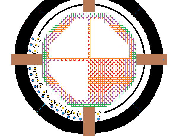
The following diagram shows a plan view of the FNR primary sodium pool.
Each colored square on this plan view represents a fuel bundle space allocation. The red squares are for active movable fuel bundles. The purple squares are for fixed square passive bundles. The inner black ring at the primary sodium pool perimeter consists of 48 pairs of primary sodium pipes which connect to the intermediate heat exchangers.
Note that in the concentric rings of heat exchange pipes there are four gaps in front of air locks that are 1 m wide to permit insertion, removal and replacement of fuel bundles.
The following diagram shows a side elevation of the FNR.
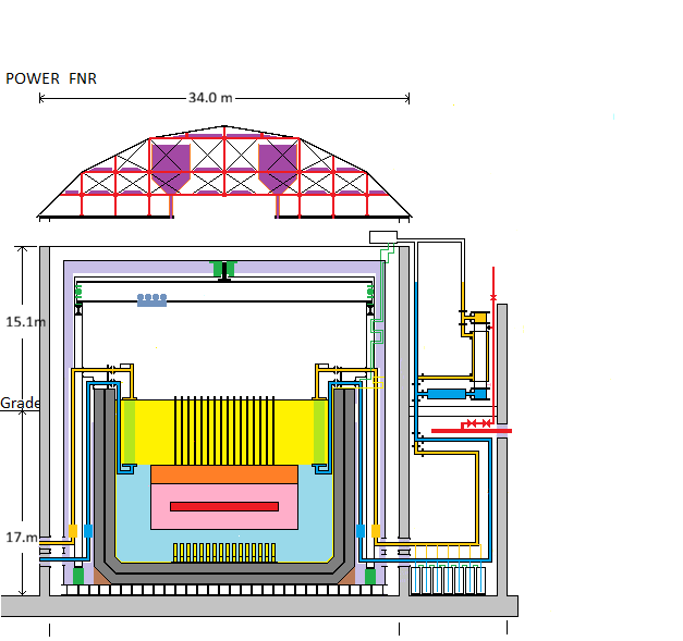
For diagramatic simplicity, the air locks and the open steel lattice supporting the fuel bundles are not shown.
Only 1 of 48 identical heat transfer loops is fully detailed.
Color Code:
Red - Reactor Core, Steam Main
Pink - Reactor Blanket
Orange- Fuel Tube Plenum
Gold- Warmer NaK pipe
Yellow- hot sodium, hydraulic sodium tube, hydraulic lifter
Light Green - Intermediate Heat Exchange tubes
Dark Green - Hot wall thermal brake support, polar gantry bearings,
Light Purple - Fiber Ceramic Insulation
Dark Purple - NaCl Reservoir
Light Blue- cool sodium
Dark Blue - Cooler NaK Pipe
Light Gray - Concrete
Dark Gray - Fire Brick
Black - Steel Outline
The bottom and sides of the primary sodium pool are lined with stainless steel sheet and are thermally isolated from the environment by a 2 m thick layer of granular NaF.
Note the fuel tube 1.6 m high plenum region above the upper blanket zone.
Not shown is the open steel lattice that positions, supports and stabilizes the fixed octagonal fuel bundles. The 340 ____movable fuel bundle actuators are located within this lattice. The fuel bundle assembly weight is distributed over the primary sodium pool floor using horizontal rectangular structural steel tubes each 14 inches X 6 inches X 0.625 inches. The fuel bundles are stabilized by the octagonal fuel bundles being set in sockets and bolted to their nearest neighbours at their top corners.
Note the 340____ X (7.5 m long indicator tubes) that reach above the top surface of the primary liquid sodium. Each indicator tube is open at the bottom, has drain holes through its walls about 1.6 m from its top and has gas tight hollow walls that make it buoyant with 1.5 m of the tube not immersed in liquid sodium. Each indicator tube guides a sample of the rising liquid sodium from a mobile fuel bundle discharge to near the surface of the liquid sodium where its temperature is easily measured by remote infra red spectrum sensing. The hollow annular space between the inner and outer walls of the indicator tube provides a route for gamma rays originating in the reactor to find their way to the surface of the liquid sodium and then reach the overhead monitoring instrumentation. The height of the top of an indicator tube above the surface of the primary liquid sodium shows the amount of insertion of the corresponding mobile square fuel bundle in the fixed fuel bundle matrix.
Not shown above the primary sodium pool is the electro-optical system which gathers active fuel bundle status data from the indicator tubes.
Note that above the primary sodium pool is a 10 tonne rated gantry crane used for ongoing moving and positioning fuel tube bundles and for installing the primary sodium pool sections and the primary sodium pipes.
The primary liquid sodium, after being cooled by an intermediate heat exchanger, flows down the primary sodium return pipes to the bottom of the primary sodium pool.
TOTAL REACTOR:
FNR TUBE BUNDLE ASSEMBLIES:
As shown on the web page titled FNR PRIMARY LIQUID SODIUM FLOW. This viscous flow limits the FNR power output.
SHUNT HEAT FLOW IN THE PRIMARY LIQUID SODIUM POOL:
The transition region between the hot liquid sodium and the cool liquid sodium is estimated to be 1.0 m thick. Assume that the temperature difference between the hot liquid sodium and the cool liquid sodium is 150 degrees C. The thermal conductivity of liquid sodium is 73 W / m-K. Hence the conducted vertical shunt heat flow is:
73 W / m-K X (1 MW / 10^6 W) X 415 m^2 X (150 K / 1.0 m) = 4.54 MWt
This shunt heat leakage is about 0.48% of full load thermal power.
At steady state conditions the primary sodium mass flow rate through the reactor should equal to the primary sodium mass flow rate through the intermediate heat exchanger.
UPPER TEMPERATURE LIMIT:
When the reactor is operating at full rated power the liquid sodium temperature discharged from the top of the active fuel tube bundles must be less than 910 F or 488 C (Til & Yoon Figure 7-2, P. 149).
REACTOR CORE DESCRIPTION:
The steel fuel tubes are 6.0 m long. The steel fuel tubes are sealed closed at both the top and bottom ends.
Each fuel bundle is supported by a square steel grating which is firmly attached to the four corner girders. There are concentric square rings of 0.5 inch OD vertical steel fuel tubes on 0.625 inch square centers. The fuel tubes of each fuel bundle are position stablized by the bottom grating, the shroud, diagonal plates and the wire winding.
Each tube bundle is laterally stabilized by is shroud and by adjacent fuel bundles. The tube bundles are placed in position by the gantry crane that spans the width of the pool. The weight of the tube bundle assemblies is borne by the pool floor. The tube bundles are repositioned or replaced from time to time using the gantry crane and remote manipulation.
The first step in tube bundle replacement is reactor shutdown and disconnection of the indicator tube. Then the corner bolts are removed. Then the gantry crane lifts the selected fixed tube bundle by the height of its frame insertion (~ 0.2 m) before moving the bundle horizontally to a perimeter storage position. During this process the spent fuel bundle remains covered by about 5.6 m of liquid sodium. The spent fuel bundle is moved to a perimeter storage position where it is mounted on another socket. The spent fuel bundle remains for six years in the liquid sodium until it loses most of its fission product decay heat. Then the spent fuel bundle is lifted out of the primary sodium pool for fuel reprocessing. Note that to access interior fuel bundles it is necessary to temporarily move other fuel bundles out of the way. There must be enough spare fuel bundle mounting positions around the reactor perimeter to permit accessing central fuel bundles.
MOVABLE FUEL BUNDLES AND INDICATOR TUBES:
Each movable fuel bundle has associated with it an indicator tube. During normal reactor operation this mobile bundle is positioned by liquid sodium pressure applied to its actuator. There are piston rings to achieve a good sliding seal between the piston OD and the ID of the actuator hydraulic cylinder. By appropriate active fuel bundle control portion positioning the reactor thermal load is evenly distributed.
Each movable fuel bundle has an attached indicator tube which indicates both the vertical position of the control portion and the fuel bundle liquid sodium discharge temperature. The indicator tube also provides a gamma ray/neutron propagation path for indicating fuel bundle power.
|THERMAL ANALYSIS:
The contemplated FNR is rated at 1000 MWt using HT-9 fuel tubes with a theoretical stress safety margin of over 2:1. At full rated power the maximum core rod temperature should normally be about 510 C. The fuel tubes heat an atmospheric pressure primary liquid sodium coolant that at full load is everywhere less than 440 degrees C.
These temperatures allow for a 10.0 deg C temperature drop across each HT-9 steel fuel tube wall and a 45 deg. C temperature drop between the inner HT-9 steel wall and the interior of the core fuel rod. Note that within the reactor flow channels the liquid sodium flow is laminar, so there may be a 5 degree C temperature difference between the fuel tube outside wall temperature and the average passing liquid sodium temperature.
The primary liquid sodium pool heats an intermediate liquid sodium heat transport loop that normally operates from 330 C to 450 C. In the steam generator of the contemplated FNR at full load the water temperature is about 320 C and the corresponding saturated steam pressure is about 11.25 MPa. This pressure is held constant by a discharge pressure regulating valve. If this valve fails to open the steam generator pressure relief valve should trip at ~ 12 MPA.
The chosen steam temperature and pressure allows FNR operation with a cooling tower heat sink. The heat sink temperature is typically 100 degrees C. The steam discharge temperature is typically 400 C. Hence the maximum possible Carnot efficiency is:
(400 C - 100 C) / (273 K + 420 C) = 300 / 693 = 0.4329
With practical turbogenerator equipment the average electrical generation efficiency is about half the Carnot efficiency or about 0.2164. Under best case operation it is about 0.30.
Thus the average electricity output will be 216.4 MWe. The best case electrical output will likely be about 300 MWe. This electricity output will drop in the winter but rise in the summer as the thermal load temperature changes.
The pressure within each secondary sodium heat transport loop is controlled by the expansion tank argon head pressure that operates at about 0.5 MPa. The secondary liquid sodium pressure is kept sufficiently high that in the event of a sodium/salt heat exchanger tube rupture the potential sodium leakage flow from the secondary sodium loop to the water is minimized and hydrogen generation is confined to the salt side of the steam generator which is vented to the atmosphere.
FNR CONSTRUCTION:
The peak temperature in the primary liquid sodium pool is about 460 degrees C. Due to this high temperature conventional cement materials that set up via absorption of water of hydration are unsuitable for thermally unprotected liquid sodium containment.
Ideally the cavity for the liquid sodium pool should be cut from bed rock. The entire cavity should be above the highest local water table.
Near the cavity walls the drill holes and explosive used should be chosen to minimize cracking of the remaining rock. The bedrock cavity should be about 49 m square X 19 m deep. The outside of the concrete below grade should be sealed with hot bitumen.
The bedrock base is leveled with igneous rock gravel. This gravel bed must be gravity drained. On top of the gravel foundation is laid 2 m of concrete, then a layer of structural steel I beams 1 m high that will support the liquid sodium pool, reactor and fire brick while permiting cooling air to circulate beside and beneath the pool to remove heat conducted through the fire brick.
The concrete side walls are then formed up to 15 m above the pool deck level.
On top of the supporting I beams is the stainless steel sheet that forms the outer liquid sodium containment floor. External vertical I beams with horizontal spreaders reinforce the pool outer vertical side walls. The pool outer sheet steel vertical side walls are precisely positioned using threaded rods with turnbuckles that are attached to the adjacent concrete face. The details of this steel wall construction are similar to the construction of the hull of a ship.
The water tightness and strength of the outer steel wall and its supporting members should be demonstrated by temporarily filling the outer stainless steel wall with water.
Inside the outer sheet steel liquid sodium containment wall is a 2 m thickness of fire brick to provide the thermal insulation between the inner and outer steel walls of the liquid sodium pool. Suitable lava rock for forming this fire brick is plentiful on the main island of Hawaii. The saw cutting of the lava rock must be numerically controlled to be dimensionally accurate so that there are no gaps between the fire bricks. If the inner stainless steel containment wall for liquid sodium leaks the amount of liquid sodium that flows into the space between the inner and outer steel walls must be low and the thermal leakage to the outer stainless steel liquid sodium containment wall must be minimal. The fire brick used must be rated for use over 500 degrees C and should not be reduced by hot liquid sodium.
HEAT LEAKAGE:
The maximum ongoing heat leakage through 2 m of fire brick can be estimated assuming a brick thermal conductivity of 0.5 W / m-K. Thus:
Heat leakage = (Area / thickness) X (0.5 W / m-deg K) X (430 deg K)
= {[Pi (11.5 m)^2 + Pi (2)(11.5 m) (15.5 m)] / 2 m} X (0.5 W / m-deg K) X (430 deg K)
= {[1535 m^2] / 2 m} X (0.5 W / m-deg K) X (430 deg K)
= 0.165 MWt
which is the maximum ongoing parasitic heat load from the reactor that must be removed by air circulation. The effective air duct cross sectional area is 27 m^2. The maximum allowable air temperature rise is about 10 degrees C. The heat capacitry Cp of dry air at 300 degrees K is:
Cp = 1.005 kJ / kg-K.
The density of air is: 1.225 kg / m^3
The heat flow is given by:
0.165 MWt X 10^6 J / s-MWt = 27 m^2 X V m / s X 1.225 kg / m^3 X 1.005 kJ / kg-K X 1000 J / kJ X 10 K
or
V = [(0.165 X 10^6 ) / (27 X 1.225 X 1.005 X 10^4)] m / s
= 0.4965 m / s
which is an acceptable ongoing ventilation air flow velocity.
Inside the 2 m of fire brick is the inner liquid sodium containment wall which is fabricated from stainless steel sheets.
The inner and outer sheet steel walls are tied to the fire brick via thin steel rods that penetrate several brick layers before reaching a tie plate situated between adjacent brick layers.
The water tightness and strength of the inner steel wall should be confirmed by temporarily filling the inner steel wall with water.
In normal operation the inner stainless steel sheet vertical walls are in tension. In the event of an inner wall failure the outer wall will become in tension. Hence both walls must be sufficiently thick to be rated for the hydrostatic stress potentially imposed by the liquid sodium.
In normal operation the outer steel wall and its components are only slightly above room temperature. We must be concerned about long term corrosion of the outer steel wall due to it being exposed to an ongoing flow of cooling air drawn from the outside.
Another potential concern is wall stress and wall movement during earth quakes. The steel rods between the outer wall reinforcing I beams and the concrete wall should be sufficiently strong and resiliant to be earthquake tolerant.
Thus the liquid sodium has four hydraulically tested containment barriers, the inner stainless steel wall, the outer stainless steel wall, the concrete wall and the bedrock or fill cavity.
The approximate volume of primary liquid sodium pool is:
Pi X (10 m)^2 X 15.0 m = 4712.4 m^3
which weighs about:
0.927 X 4712.4 = 4368 tonnes.
REACTOR SECTION FLOOR LINER:
An FNR designed for utility power production has many thousands of fuel rods. Sooner or later through accident, negligence or malevolent behavior a defective fuel bundle and/or related reactivity control system will be loaded into the reactor. In these circumstances a significant concern is fuel melting. If a steel fuel tube fails high density fuel rods, droplets or pellets might sink through the liquid sodium and will collect on the pool floor. It is essential that this material does not accumulate together sufficiently to form a critical mass. Thus the tube bundle support frame should be covered with a liner that has a high neutron absorption cross section and has controlled size bumps or cavities so that a critical mass cannot form. There should be a practical means of selectively removing and cleaning portions of this liner.
PRIMARY SODIUM CONTAMINANT FILTERING:
A power FNR will contain about 4700 m^3 of primary liquid sodium. In spite of best efforts to prevent sodium contamination the hot liquid sodium will gradually become contaminated. Hence a dedicated sump pump is required to run continuously to pump liquid sodium out of the bottom of the primary sodium pool, through a cleanup filter apparatus and back into the pool.
Each reactor tube bundle contains numerous narrow internal sodium flow channels. Thus it is imperative that there be a filter process that constantly removes sodium contaminants. The primary sodium filter must trap and remove all particulate matter with any dimension in excess of (1 / 32) inch. This filter system must run for a long time before the steel tube bundles are inserted into the liquid sodium.
eg if the sump pump runs at 0.5 m^3 / minute the time required to pump one pool volume is:
(4700 m^3) X (1 minute / 0.5 m^3) X (1 hour / 60 minutes) X (1 day / 24 hour) = 7 days.
Hence it will require at least a month to appreciably filter the liquid sodium.
Over time the liquid sodium will gradually become polluted with unwanted material including magnesium particles, radio active fuel, other metals, sodium oxide, sodium hydroxide, etc. The contaminants will include:
Na2O, NaOH, Na3N, NaNO2, NaNO3
Na2O must be removed by density separation and filtering. It has a specific gravity of 2.27 and sublimates at 1275 degrees C.
NaOH melts at 318.4 degrees C and has a boiling point of 1390 degrees C. It has a specific gravity of 2.130. It can be removed by density separation and filtering at a temperature less than 318 degrees C. NaOH may tend to form on the surface of the cooler parts of the intermediate heat exchange bundles if the pressure in the steam generator falls below 11.25 MPa causing the temperature of the return secondary sodium to fall below 320 degrees C.
Na3N dissociates at 300 degrees C and hence nitrogen accumulates in the cover gas. At temperatures below 300 C the nitrogen will react with the sodium. Then Na3N can be remved by filtering.
NaNO2 MP = 271 degrees C, dissociates at 320 deg C, SG = 2.16, can be removed by filtering at less than 271 degrees C or by cryogenic separation of cover gas.
NaNO3 MP = 306.8 deg C, dissociates at 380 deg C, SG = 2.261, can be removed density separation and filtering at less than 306.8 degrees C
The primary liquid sodium temperature must drop below 300 degrees C to permit complete contaminent removal by filtering. Hence the filter system inlet should be at the intermediate heat exchanger primary sodium discharge where the primary liquid sodium temperature is lowest. At this point the pool floor should be deepest. To clean the intermediate heat exchange tubes it is necesary to run the reactor at part load to raise the intermediate sodium return temperature.
SAFETY SYSTEM CONCEPT:
For safety reasons the pressure of the argon gas over the secondary sodium is kept slightly higher than the steam pressure. Any unanticipated change in secondary sodium level in the secondary sodium expansion tank indicates a tube leak somewhere, as does any presence of hydrogen in either the steam / condensate circuit or the secondary sodium circuit. In response that heat transport circuit is shut down is shut down and steam/hydrogen is released via the steam circuit vent. This safety concept keeps both water and hydrogen out of the secondary sodium circuit where they could potentially cause catastrophic damage to the pipes and/or intermediate heat exchanger by liquid sodium fluid hammer.
The reactor has 48 independent intermediate heat transport loops. In the event that one heat transport loop has any sort of fault that loop can be shut down and isolated while the other heat transport loops continue to operate. Each heat transport loop has its own intermediate heat exchange bundles, steam generator, and secondary liquid sodium circulation pump. Each group of 3 or 4 heat transport loops has its own turbogenerator, condenser, condensate injection pump. Cooling towers, transformers, switchgear and auxillary power are shared.
A steam pressure in excess of 12.0 MPa should also trigger a heat transport loop shut down.
The maximum permitted liquid sodium temperature in normal circumstances is 500 deg C. At that temperature the yield stress of the steel fuel tubes and pipes starts to decrease. If the primary liquid sodium temperature exceeds 510 deg C at any point that temperature should trigger a cool reactor shutdown via mobile fuel bundle withdrawal.
If for some reason the release of the mobile fuel bundles fails to shut down the reactor and if the heat removal rate is insufficient the primary liquid sodium temperature will rise until thermal expansion of the core fuel bundles reduces the core reactivity, which will by itself shut down the reactor. However, even with a total fission shut down it is necessary to maintain sufficient cooling to remove fission product decay heat.
STRUCTURAL ISSUES:
As calculated on another web page the mass of each fuel bundle is about 3 to 4 tonnes.
Clearly the gantry must be rated for at least 10 tonnes to allow for the circumstance when two or three fuel bundles stick together.
The corresponding floor load pressure due to the fuel bundles is:
5100 kg / 0.2025 m^2 = 25 tonne / m^2
The floor load pressure due to the liquid sodium is:
15.5 m X 0.927 tonne / m^3 = 14.4 tonne / m^2
There is an additional floor load due to the steel fuel bundle support frames.
There is a pressure due to fire brick under the pool of about:
2 m X 2 tonnes / m^3 = 4 tonnes / m^2
It is clear that the total ground load, including the pool structure, is ~ 50 tonnes / m^2, which requires a suitable bedrock foundation. The corresponding ground pressure is:
(54 X 10^3 kg / m^2) X 9.8 m /s^2 / 1 m^2 = 529 X 10^3 Pa
= 529 kPa________
The load bearing capacity of shale bedrock is believed to be about 5000 kPa
Under the inner pool floor liner is a 2 m thickness of solid brick, then the outer pool liner, then a 1 m layer of I beams resting on a 2.0 m thick concrete/gravel foundation with a sump pit. The I beams must be long term protected from corrosion.
PLUTONIUM DOUBLING TIME:
An issue of great importance in large scale implementation of FNRs is the FNR run time required for one FNR to breed enough excess Pu-239 to allow startup of another identical FNR. This time may be calculated using the approximation that each plutonium atom fission releases of 3.1 neutrons of which 2.5 neutrons are required for sustaining reactor operation leaving 0.6 neutrons for breeding extra Pu-239. Thus one atom of Pu-239 has to fission to form 0.6 atoms of extra Pu-239.
Hence the plutonium doubling time, which the time required to double the available amount of plutonium via breeding within the FNR is:
(10 / 6) X (time to consume the initial Pu supply)
= [(10 / 6) X (1 cycle time )] / 0.59
= 2.825 (1 fuel cycle time)
= 2.825 X (47.78 years)
= 136 years
This is the time required for one FNR to form enough excess Pu to allow starting another FNR. Clearly this doubling time is too long to enable rapid deployment of FNRs.
With large scale implementation of FNRs the available supply of plutonium and trans uranium actinides will soon be exhausted. Hence the issue of the Pu-239 doubling time physically constrains the rate of growth of the FNR fleet.
Thus FNRs are viable for disposing of transuranium actinides but due to the Pu-239 doubling time will not in the near future provide enough power capacity for complete displacement of fossil fuels.
FUEL BUNDLE TRACKING:
Each fuel bundle requires an individual code identifier to allow tracking of its neutron exposure history.
FISSION PRODUCT DECAY HEAT REMOVAL:
One of the most important aspects of reactor design is provision for fission product decay heat removal under adverse circumstances. If an event occurs which causes a sudden reactor shutdown the reactor will continue to produce fission product decay heat at 5% to 10% of its full power rating. Hence it is essential to ensure ongoing removal of fission product decay heat under the most adverse circumstances.
Hence:
1) Under no circumstances, including a sodium pool inner wall leak, should the liquid sodium level ever fall to the point that the fuel tubes are not fully immersed in liquid sodium.
2) The fire brick fill between the inner and outer pool walls must be designed such that if the inner wall fails and the liquid sodium leaks into the space between the inner and outer most walls, the sodium pool surface level will not drop below the tops of the upper blanket rods.
3) There must be sufficient natural intermediate liquid sodium circulation to remove fission product decay heat from the primary liquid sodium pool;
4) In the event of a secondary liquid sodium circuit fault it is essential that reactor cooling be maintained. Hence multiple redundant secondary heat transport systems are required. The current design contemplates 16 independent heat removal systems.
PRIMARY SODIUM TEMPERATURE MAINTENANCE:
To prevent prolonged equipment restart problems due to sodium freezing it is essential to keep the primary liquid sodium above 100 degrees C at all times. Hence, there should be at least four 0.5 MWt oil fired boilers on site connected to separate secondary liquid sodium circuits to ensure maintenance of the primary liquid sodium pool temperature.
FNR THERMAL TIME CONSTANT:
The volume of primary liquid sodium pool is about:
Pi X (10 m)^2 X 15.0 m = 4712 m^3
The sodium volume displaced by fuel tubes is:
FIX FROM HERE
640 bundles X 433 tubes / bundle X 6 m X Pi X (.25 inch)^2 X (.0254 m / inch)^2
+ ________ bundles X 556 tubes / bundle X 6 m X Pi X (.25 inch)^2 X (.0254 m / inch)^2
= 640 bundles X 433 tubes / bundle X 7.600 X 10^-4 m^3 / tube
+ ____ bundles X 556 tubes / bundle X 7.600 X 10^-4 m^3 / tube
= 231.52 m^3 + 141.98 m^3
= 373.5 m^3
The primary liquid sodium volume displaced by the intermediate heat exchange bundle tubes is:
48 bundles X 1648 tubes / bundle X 6.0 m X Pi X (.25 inch)^2 X (.0254 m / inch)^2
= 40.06 m^3_______
The primary liquid sodium volume displaced by the immersed pipes and headers is:
48 X 12 m X Pi X (8 inch X .0254 m / inch)^2 = ~ 49.8 m^3.____
Thus the actual volume of primary liquid sodium is about:
6440 m^3 - 373.5 m^3 - 40.06 m^3 -49.8 m^2 = _______ m^3
The maximum primary liquid sodium temperature slew rate at rated power is:
(921 MWt X 10^6 J / s-MW) / [(_____ m^3 X 927 kg / m3 X 1000 gm / kg X 28.230 J / mole deg K X (1 mole / 22.9897 gm)]
= (921 X 10^6 / s) / [____ X 927 X 1000 X 28.230 / deg K X (1 / 22.9897 )]
= [921 X 10^6 deg K / s X 22.9897] / [____ X 927 X 1000 X 28.230]
= 0.18 deg K / s
FIX
= 0.18 deg K / s X 60 s / minute = 10.83 deg K / minute
Thus when operating at full rated power it will take about one half hour to raise the reactor from an off condition at 120 degrees C to an on condition at an average temperature of 400 degrees C.
Some important physical properties of water, sodium and argon, are:
| PROPERTY | WATER | SODIUM | ARGON |
|---|---|---|---|
| Liquid Thermal Conductivity: | 0.58 W / m-deg C | 142 W / m-deg C | |
| Density Rho: | 1.0 kg / lit | .927 kg / lit | 1.784 g / lit@101.025 KPa, 0 deg C |
| (1 / Rho) dRho / dT: | 2.71 X 10^-4 / deg K | ||
| Heat Capacity (J / mol deg K): | 75.24 | 28.230 | 20.786 |
| Heat of Vaporization@101 kPa: | 40.68 kJ / mole | 97.42 kJ / mole | |
| Molecular Weight (gm / mole): | 18 | 22.9897 | 39.948 |
| Viscosity Muv (kg / m-s): | 7 X 10^-4 | ||
| Melting Point@101kPa (deg C): | 0 | 97.72 | |
| Boiling Point@101 kPa (deg C): | 100 | 883 | |
| Vapor Pressure@46 C: | 10.094 kPa | ||
| Vapor Pressure@70 C: | 31.176 kPa | ||
| Vapor Pressure@100 C: | 101.32 kPa | ||
| Vapor Pressure@134 C: | 303.93 kPa | ||
| Vapor Pressure@180 C: | 1001.9 kPa | ||
| Vapor Pressure@234 C: | 3005.9 kPa | ||
| Vapor Pressure@281 C: | 6510.5 kPa | 1 Pa | |
| Vapor Pressure@311 C: | 9995.8 kPa | ||
| Vapor Pressure@344 C: | 15.342 MPa | 10 Pa |
STEAM GENERATOR CONNECTION:
A 12.75 inch OD (10.____ inch ID) liquid sodium pipe from the intermediate heat exchanger to feed its respective adjacent steam generator. Each such pipe feeds approximately _____ X 0.500 inch OD X .065 inch wall tubes in each steam generator.
Space must be left clear to allow steam generator removal and replacement via an overhead crane. Thus around the reactor building are 8 heat exchange galleries.
Note that The steam generators likely require internal floating tube manifolds to minimize longitudinal thermal stress. If both the tubes and the shell are fabricated from Inconel 600 the steam generators are expensive.
At the water inlet and steam output ports on the shell side the 2 foot diameter steam generator must be heavily reinforced. The shell must safely contain the steam pressure. The steam pressure compresses the 0.500 inch OD tubes which operate at a slightly higher internal pressure.
The connections to the tube side of the steam generators must be high pressure liquid sodium tight.
SECONDARY SODIUM VOLUME:
The volume of each intermediate sodium circuit can be estimated by assuming that everywhere along that circuit the cross sectional area is approximately the same as the cross sectional area of a 12.8 inch_____ inside diameter pipe.
Thus the minimum pipe length equivalents are:
Intermediate heat exchanger = 18 m
Steam generator = 18 m
Horizontal pipes = 2 X (4 m + 8 m + 4 m) = 32 m
Vertical pipes = 2 X 15 m = 30 m
Hence total equivalent pipe length = 98 m
Pipe volume = Pi (6.4 inch)^2 X 98 m X (.0254 m / inch)^2 = 8.135 m^3
Thus the total secondary sodium volume is about:
32 X 8.135 m^3 = 260.32 m^3
Note that the cushion tank and drain down tank volumes are additional.
SUMMARY OF MAJOR MATERIAL REQUIREMENTS FOR ONE 1000 MWt FNR:
____Fixed active fuel bundles
____ Movable active fuel bundles
_____Fixed passive fuel bundles
____ Movable passive fuel bundles
48 X 20 foot lengths of 24 inch OD thick wall steel pipe rated for 12 MPa working pressure for steam generators
48 X 20 foot lengths of 24 inch OD medium wall steel pipe rated for ___ MPa working pressure for sodium/slat heat exchangers
3200 m of 16.0 inch OD______, 1.594 inch wall steel pipe rated for 12 MPa working pressure for secondary sodium
48 liquid sodium intermediate loop induction pumps 16 inch nominal pipe OD, 12 inch pipe ID.
48 X 1648 = 52,736_____ X 20 foot inconel 0.5 inch OD intermediate heat exchange tubes rated for 12 MPa working pressure at 500 deg C
48 intermediate heat exchanger top headers;
48 intermediate heat exchanger bottom headers;
32 X 1452 = 46,464 0.5 inch outside diameter 0.065 inch wall inconel steam generator tubes rated for 12 MPa working pressure at 500 deg C
48 steel columns X 6 m high for supporting the intermediate heat exchange bundles
48 sets of intermediate heat exchange inter-column braces
48 intermediate heat exchanger support column bases
96 steam generator tube sheets each about 24 inch diameter
96 steam generator end caps, 24 inch diameter
48 steam generator barrels, 24 inch diameter
48 X 1400____ steam generator tubes
48 expansion tanks
48 liquid sodium drain down tanks
20,000 m^3 of outside wall surround fill;
______
Pi {[15 m X (12 m)^2] - [13 m X (10 m)^2]} = Pi {2160 m^3 - 1300 m^3} = 2702 m^3 fire brick
452 m^2 = primary sodium pool outside bottom sheet stainless steel;
380.1 m^2 = primary sodium pool middle bottom sheet stainless steel;
314.16 m^2 = primary sodium pool inside bottom sheet stainless steel;
Pi X 24 m X 15 m = 1131 m^2 primary sodium pool outside wall sheet stainless steel;
Pi X 22 m X 14 m = 968 m^2 primary sodium pool middle wall sheet stainless steel;
Pi X 20 m X 13 m = 817 m^2 primary sodium pool inside wall sheet stainless steel;
4715 m^3 ____concrete;(reactor enclosure only)
Inner wall cover stainless steel 4 X 11 m X 26 m = 1144 m^2
Inner ceiling cover stainless steel 26 m X 26 m = 676 m^2
Pool Deck = (26 m X 26 m) - Pi (10 m)^2 =
Outer wall cover stainless steel 4 X 12 m X 28 m = 1344 m^2
Outer ceiling stainless steel cover 28 m X 28 m = 784 m^2
Fiberfrax insulation 1344 m^3 + 784 m^3 = 2128 m^3
Exhaust fans;
48 independent argon pressure systems;
4 hot oil boilers for primary sodium melting via intermediate heat exchange systems;
360___ laser range finders;
IR temperature measurement system;
Gamma ray camera system;
1 set of fuel bundle support stands, 1068 fuel bundle capacity with 640 liquid sodium hydraulic control fittings;
340 ____active fuel bundle control portion hydraulic positioning systems;
48 secondary sodium drain down tanks;
48 secondary sodium expansion tanks;
804 m^3 _____ingeous rock gravel for foundation, 2 m thick;
28 X 28 m long X 1 m deep X 1 m wide declining length I beams for bottom support of primary sodium pool and its contents;
~ granite rock property;
>
~ 20,000 55 gallon open top steel drums with covers for emergency sodium storage;
~ 8 X steam pressure control sustems
~ 8 X 40 MWe steam turbogenerators;
~ 8 X 100 MWt condensers;
~ 4 X 140 MWt natural draft dry cooling towers;
~ 8 sets of switchgear with contactors;
~ 8 sets of synchronizing equipment;
~ 8 sets of power control equipment;
~ 8 X 40 MVA 3 P transformers
- 2 argon cryogenic systems;
- 4 silo enclosed argon bladder tanks, each 900 m^3 capacity with protective gas heat exchangers
The cost of the aforementioned items installed x 2 is the floor price for a FNR.
This web page last partially updated June 3, 2026.
| Home | Energy Physics | Nuclear Power | Electricity | Climate Change | Lighting Control | Contacts | Links |
|---|