| Home | Energy Physics | Nuclear Power | Electricity | Climate Change | Lighting Control | Contacts | Links |
|---|
FNR INTERMEDIATE HEAT EXCHANGE TUBE BUNDLE:
The main purpose of an Intermediate Heat Exchange Tube Bundle is to transfer heat from the liquid sodium to lower pressure liquid NaK. However, on system black start the direction of heat flow is reversed, in which case the NaK heats the sodium. Around the sodium pool perimeter there are theoretical positions for 56 intermediate heat exchange tube bundles but only 48 of these positions are used due to the presence of physically displacing airlock related load/unload trays. The 48 intermediate heat exchange tube bundles are immersed in the liquid sodium such that the upper manifold of each tube bundle is only just barely immersed.
These heat exchange tube bundles isolate the radioactive liquid sodium from the lower pressure non-radioactive liquid NaK. The intermediate heat exchange tube bundles also serve as a barrier to other radioactive species in the event of a fuel tube leak. In the event of an intermediate heat exchange bundle leak the lower pressure of the NaK ensures that radioactive species migrate from the sodium into the NaK. Radioactivity in the circulated NaK trips an alarm that causes shutdown and drain down of this NaK loop.
In the event of a sodium fire the intermediate heat exchange top manifolds displace liquid sodium in a manner that prevents liquid sodium surface combustion at the manifold location.
To allow for the bottom feed elbows and 8.0 inch of pipe flange, when the system is cold the axes of the vertical intermediate heat exchange bundle pipe connections to the manifolds should lie on a circle with a radius:
393.7 inch - 8.0 inch - 16.0 inch - 40.0 inch = 329.7 inch.
Measured from the sodium pool inner wall the distance to the center of the vertical feed pipes is:
Hence the feed pipe centre circle diameter is:
20 m ~ 2(1.625 m) ~ 16.75 m
Hence the maximum manifold arc length at the feed pipe location is:
Pi (16.75 m) / 56 = 0.9396 m = 36.995 inch
At the wide end of the manifold the system radius from pool center is:
393.7 inch - 16.0 inch - 8.0 inch = 369.7 inch ~ 9.390 m
Based on 16 inch pipe flange design this bolted manifold needs an 8.0 inch allowance for the flange with bolts and sealing gasket. Hence the system radius from pool center at the small end of the manifold becomes:
329.7 inch - 16 inch = 313.7 inch = 7.968 m.
This is the outer radius of the open path for moving fuel bundles.
The manifold arc length at its small end is:
2 Pi (313.7 inch) / 56 = 35.197 inch ~ 35.2 inch
This path width is not sufficient for moving intermediate heat exchange bundles. Hence the polar gantry must be able to lift the intermediate heat exchange bundles clear of the installed fuel bundles. This issue sets the ceiing height above the pool deck.
(Ceiling height above pool deck) - (4 m gantry allowance) + 1.0 m + (depth to fixed fuel bundles) > (length of intermediate heat exchange bundle)
The distance along the manifold outer radius arc is:
369.7 inch X 2 X Pi / 56 = 41.480 inch.
Assume that the manifold has a 8.0 inch wide flange for sidewall, gasket compression and bolting.
Inside the manifold the outer arc length is:
[(369.7 inch - 8 inch) X 2 Pi / 56] - 2 (8 inch) = 24.58 inch
Inside the manifold the radial distance to the small end of the inner space is:
369.7 inch - 313.7 inch - 2(8.0 inch) = 40.0 inch
At the feed pipe circle radius of 329.7 inch the inner arc length is > 16 inch.
At the small end of the manifold the internal arc length is:
35.2 inch - 2 (8 inch) = 19.2 inch
The external footprint of the manifold has an area given by:
Pi [(369.7 inch)^2 - (313.7 inch)^2] / 56
= Pi [136678.09 - 98497.69] / 56
= 2146.96 inch^2
The outside radial length of the manifold is:
369.7 inch - 313.7 inch = 56 inch
The manifold foot print area occupied by the flanges is:
[2 (56 inch)] 8 inch + [41.48 inch - 2 (8 inch)] 8 inch + [35.2 inch -2(8 inch)] 8 inch
= [112 inch + 25.48 inch + 19.2] 8 inch
= 1253.44 inch^2
Hence the manifold area available for tubes is:
2147 inch^2 - 1253.44 inch^2 = 893.56 inch^2
The desired tube open area is:
Pi (8.0 inch - .375 inch)^2
= 182.65 inch^2
One of the challenges in intermediate heat exchange bundle design is relief of thermal stress that arises from the large temperature difference between the NaK supply temperature (450 deg C) and return temperatures (330 deg C).
The intermediate heat exchange tube bundle is suspended from above so that it is free to move during thermal expansion and contraction.
SPECIFICATION:
Material = 316L stainless steel. Gaskets = Nickel or Chromium coated soft copper connecting pipe 16 inch OD, 3/8 inchwall,elbow inside radius = 16 inch,elbow outside radius = 32 inch, flanges have 2 concentric circles of bolts.
Is there enough heat transfer area?
Is viscosity load OK???
Assume tubes 3/4 inch ID, 7 / 8 inch ODMaximum number of tubes / track = 24.58 inch / 1.25 inch = 19.66 = 19
Minimum number of tubes / track = (19.2 inch / 1.25 inch) = 15.36 = 15
Average number of tubes / track = 17
Hence total number of tubes / manifold = 32 tracks / manifold X 17 tubes/ track = 544 tubes/manifold
Open area per tube = Pi (0.375 inch)^2 = 0.4418 inch^2
Pipe open area = Pi (15.25 inch / 2)^2 = 182.65 inch^2
Hence total tube open area = 0.4418 inch^2 / tube X 544 tubes = 240.33 inch^2. This meets the required tube open area of 183 inch^2 with some margin for viscosity.
Then distance bottom goose neck goes below bottom of lower manifold is:
32 inch
Required manifold inside height = 10 inches to allow sufficient radial NaK flow.
Thus the overall height of the intermediate heat exchange bundle assembly is:
32 inch + 10 inch + 6 m + 10 inch + 1 m + 0.5 m + 48 inch + 0.5 m + 16 inch + 3 inch = 119 inch + 8 m = 11.02 m
This dimension sets the minimum inside length of an equipment transfer airlock.
Note that the top discharge fitting is a 16 inch X 16 inch X 16 inch tee which retains a recessed lifting point that can will accommodte two hooks, one for the diagonal support chain with a steel turnbuckle, the other for the gantry crane. Note that this lifting point is displaced from the vertical pipe axis to ensure that when the gantry lifts an Intermediate Heat Exchange Bundle the gantry places it in the correct orientation for insertion into an equipment transfer airlock.
The radial width of the intermediate heat exchange bundle assembly is:
72 inch + blanking plate thickness + (329.7 inch - 313.7 inch) = 88 inch + blanking plate
= 2.286 m
This dimension sets the minimum inside height of the equipment airlock assuming that the airlock top is flat. Otherwise the equipment airlock inside height must be higher.
The equipment airlock inside width must accommodate the 42 inch wide outer curve of the manifolds.
The gantry crane must be high enough to lift an intermediate heat exchange bundle on to or off its tray at pool deck level.
CONTAINED NaK VOLUME:
Contained NaK volume in tubes:
480 tubes X Pi(3 / 8 inch)^2 X 6.0 m X (.0234 m / inch)^2
= 0.8209 m^3
Contained NaK volume in manifolds:
= 2 X 10 inch X 1068.1 inch^2 X (0.0254 m / inch)^3
= 0.35 m^3
Contained NaK volume in 16 inch pipes to disconnect flanges:
Pi (15.25 inch / 2)^2 [({2 Pi X 24 inch)/ 4 + 1 m + 0.25 m + 6 m + 0.25 m + 2 Pi(24 inch / 2)} + {2 m + 2 Pi (24 inch / 4) + 1.5 m}]
= Pi (15.25 inch / 2)^2 {(2 Pi X 24 inch) + 11.0 m}
= 182.654 inch^2 [14.83 m)
= 1.746 m^3
Total NaK volume contained in intermediate heat exchange bundle:
= 0.8209 m^3 + 0.35 m^3 + 1.746 m^3 m^3
= 2.044 m^3
Intermediate heat exchange bundle heat transfer area:
480 tubes X Pi X (3 / 4 inch) X (0.0254 m / inch) X 5.7 m
= 163.74 m^2
TUBE SHEET CURLING
The temperature drop across the tube sheet thickness leads to tube sheet curling. This effect places different axial stress on central tubes than on perimeter tubes. At the top manifold the Na is consistently warmer than the NaK so the perimter of the top manifold bends down with respect to the manifold center. At the bottom manifold the NaK is consistently cooler than the Na which causes the lower mnifold perimeter to bend up with respect to the manifold center. Hence for the intermediate heat exchange bundle these two effects are additive. However, because the intermediate heat exchange bundle has no rigid shell, the outer tubes are in linear compresion whereas the inner tubes are in linear tension.
INTERMEDIATE HEAT EXCHANGE BUNDLE NaK DRAIN TUBE:
Each intermediate heat exchange bundle has a small diameter drain tube with monotonic slope running from the lowest point in the gooseneck. This tube provides nearly complete removal of NaK for service.
When it is desired to remove a particular intermediate heat exchanger argon pressure is removed from the NaK dump tank head space and is vented to the top of the NaK loop. As a result the entire volume of NaK above the pool deck drains down into the NaK dump tank.
The drain tube is then used to remove NaK from the intermediate heat exchange bundle before disconnecting the heat exchange bundle's flanges.
Hence when a heat exchange bundle is disconnected there will be little hazard due to residual NaK in the pipes and heat exchange bundle. Note that the pipes must all slope monotonically to ensure complete NaK drainage.
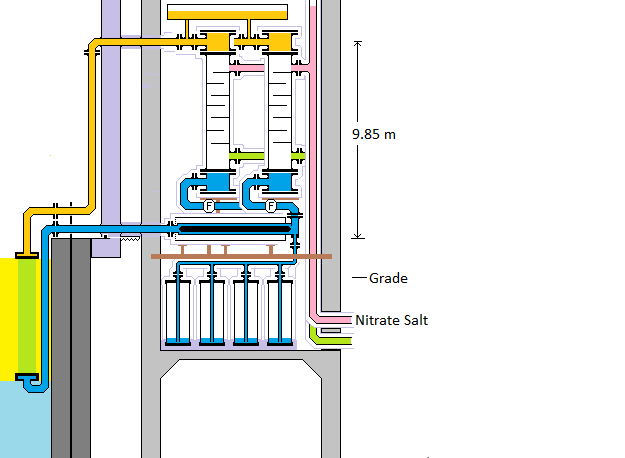
INTERMEDIATE HEAT EXCHANGE BUNDLES:
The intermediate heat exchanger is realized with a single pass vertical tube bundle.
The intermediate heat exchange bundle top manifold connects to the steam generator top manifold via a 16.0 inch OD pipe. The intermediate heat exchange bundle bottom manifold connects to the induction pump discharge via a 16.0 inch OD pipe. This pipe returns NaK at 330 degrees C. This configuration provides controlled NaK/Na heat exchange counterflow and permits removal and replacement of individual components via an overhead crane lift. For each heat transport loop there is a gravity drain to a dedicated NaK dump tank.
The intermediate heat exchange bundles can move horizontally with respect to the concrete enclosure. When the system is at operating temperature there is about a 0.15 m gap between the NaK return pipe and the sodium pool inside wall. As the system cools this gap slowly shrinks to zero due to thermal contraction of both the sodium pool liner and the NaK pipes.
The overall length of the intermediate heat exchange bundle asembly is a critical parameter as it determines the size of the corresponding airlock and tilting equipment tray.
HOOP STRESS:
As shown on the web page titled: FNR Heat Transport System if the material is 316 SS the maximum allowed material working stress at 800 degrees K is 39 MPa.
The maximum pressure within the NaK loop is also constrained by the pressure withstand capability of the intermediate heat exchange bundle manifolds. Hence the useful load bearing wall thickness is only 1.5 inch. That fully accounts for the available manifold diameter. The stress limit of the manifold cover sets the maximum possible working pressure of the NaK at Pm .
The axial force that the manifold side walls can potentially with stand is :
Pi (35.75 inch) (1.5 inch)(39 MPa).
Hence the NaK circuit is not pressure limited by the thickness of the intermediate heat exchange manifold side walls.
Hence the thicknesss of the manifold end covers is set to meet the NaK loop internal pressure rating.
MINIMUM INTERNAL MANIFOLD HEIGHT:
The 16 inch OD pipe cross section is:
Pi [8 -.375]^2 inch^2 = 183 inch^2
At the manifold input this cross section must be less than:
(16 inch) H
Hence:
H > 10 inch
MANIFOLD COVER THICKNESS:
Its end cover thickness limits the maximum working pressure of the NaK to 1.7 MPa at 527 degrees C.
GASKET CONSTRAINT:
A major constraint on the FNR NaK loop design is gasket properties. The NaK is too chemically aggressive at 475 degrees C for use of normal elastomeric gaskets. However, elastomeric gaskets can be used for low temperature hydraulic pressure testing with water.
Mechanical joints need close to optical precision fabrication. This precision is nearly essential for heat exchange bundle manifold fabrication. All the heat exchange bundle manifolds have bolted flanges. These flanges are sealed with soft metal gaskets and bolted. The intermediate het exchange bundle NaK is held at a lower absolute pressure than the surrounding liquid Na to ensure that if there is a leak then Na flows into the NaK, not vice versa.
INTERMEDIATE HEAT EXCHANGER MANIFOLD END CAPS:
The intermediate heat exchange manifold end caps might have to be cast from Haynes 617 Alloy
INTERMEDIATE HEAT EXCHANGE BUNDLE PRESSURE RATING:
The intermediate heat exchange bundle should be rated for an NaK internal working pressure of 1.8 MPa.
INTERMEDIATE HEAT EXCHANGE BUNDLES:
In the intermediate heat exchanger bundles the NaK heat flow rate must be the same as the sodium heat flow rate. However, the sodium flow cross sectional area is much larger so the sodium linear descent velocity is smaller than the NaK rise rate.
For the intermediate heat exchange bundle the end face open area is:
480 tubes X Pi [(3 / 8)inch]^2
= 183 inch^2
Hence the sodium flow into and away from the intermediate heat exchange bundles must be the equivalent in cross sectional area to a 21.5 inch inside diameter pipe..
INTERMEDIATE HEAT EXCHANGE BUNDLE TUBE CONFIGURATION:
The intermediate heat exchange tubes are Inconel 600, 20 feet (6.0 M) long. They are 0.875 inch OD, 0.750 inch ID, 0.065 inch wall thickness. The heat exchange bundles are single pass. Baffles are used to direct the sodium flow
Note that at the edge of each intermediate heat exchange bundle liquid sodium can easily flow horizontally to as to pass thrugh the bundle.
INTERMEDIATE HEAT EXCHANGE BUNDLE TUBES:
Let Pm be the maximum working pressure of these tubes. Then:
Pm (0.7500 inch) = 2 (.065 inch)(39 MPa)
or
Pm = 2 (.065 inch)(39 MPa) / 0.7500 inch
= 6.76 MPa
PROCEDURE FOR INTERMEDIATE HEAT EXCHANGE BUNDLE REPLACEMENT:
Replacing an intermediate heat exchanger involves the following steps:
a) Cool down the NaK to 120 deg C;
b) Transfer the NaK in the defective heat transport loop into the loop dump tank;
Upstream from the induction pump is a 16 inch vertical axis tee to permit complete drainage of the NaK contained within the induction pump. The lower port on this tee goes to the dump tank.
c) Disconnect both NaK service pipes at the flanged connections;
d) Immediately blank off the disconnected pipes;
e) Use the polar gantry crane to lift the defective heat exchange bundle clear of the NaK pipes, onto an airlock tray and then into an airlock;
f) Transfer the defective heat exchanger to a service vehicle;
g) Lift a replacement intermediate heat exchanger into place using the same air lock and crane;
h) Rotate the new heat exchange bundle so that its connection flanges align with the NaK service pipes;
k) Make pipe connections with appropriate high temperature rated metal gaskets. Use a laser alignment tool;
l) Test that the system holds argon pressure.
m) Insulate the piping;
n) Transfer NaK from the NaK dump tank back into the NaK heat transport loop;
INLET PIPE STRESS RELIEF:
The temperature of the NaK approaching the intermediate heat exchange inlet is about 330 degrees C. The temperature of the sodium near this inlet point may be over 400 degrees C. To mitigate thermal stress in the NaK inlet pipe this pipe may need to be sleeved to reduce material thermal stress.
MECHANICAL SUPPORT:
Each intermediadiate heat exchange bundle has a recessed lifting point attached to the top of the hot NaK discharge pipe and sufficiently along it that when the bundle supported just by the gantry is laid on a flat surface the NaK pipe flanges are on top and the gantry lifting apparatus does not clash with the hot NaK pipe discharge flange. In normal operation the weight of the intermediate heat exchange bundles is primarily borne by pool space wall mounted chain fixtures located about 6 m above the pool deck. Each intermediate heat exchange bundle is supported by two chains to provide a small amount of lateral stability. The chain fixtures are attached to vertical hot wall I beams. Each chain has a turnbuckle for fine position adjustment.
The intermediate heat exchange bundles are further supported and positioned by the radial NaK pipes, which in turn are vertically supported by a pipe stand set about 1 m away from the pool edge. The NaK pipes exert horizontal force on the hot wall and NaK pipe bellows. Note that the total force along the chains has a vertical vector component about 2 X the horizontal vector component.
FLOW CONFIGURATION:
The intermediate heat exchangers are single pass to realize counter flow operation and to minimize material thermal stresses.
Thus in the intermediate heat exchangers higher pressure NaK flows inside the vertical heat exchange tubes. If there is a NaK leak from the intermediate heat exchanger that NaK will leak into the lower pressure sodium pool.
INTERMEDIATE HEAT EXCHANGE BUNDLE CLEANING:
Immediately underneath each intermediate heat exchange bundle is an intermediate heat exchanger gooseneck. One of the functions of this goodeneck is to trap material of a higher density than NaK. Periodically when the sodium is hot the NaK induction pump is turned off and dirt from this gooseneck is removed by vacuum suction using a small diameter tube that runs from the bottom of this gooseneck to an isolation valve. The pressure of the argon above the NaK will drive the contents of the intermediate heat exchanger sump up the drain tube and into a catch basin, which is at ambient pressure.
DISCONNECTION SAFETY:
Each intermediate heat exchange bundle is fitted with a drain tube that is physically located inside the 16 inch diameter cold downflow pipe.
This tube exits at a capped side port on the 16 inch diameter pipe. If an intermediate heat exchange bundle needs to be replaced the first step is to gravity drain all the contained NaK from above the bottom of the steam generatorinto the connected the associated NaK dump tank.
To expel NaK from the intermediate heat exchange bundle tubes, after the NaK level is drained down to the level of the bottom of the steam generator positive argon pressure is applied to the system with the vents and dump tank connection blocked. That will force the remaining NaK up the service tube which can be connected to the dump tank. The remaining NaK in the intermediate heat exchanger is just that remaining in the sump drain tube.
In reality, even after this procedure is complete a small amount of NaK will remain in the bottom of the intermediate heat exchange bundle gooseneck. This small amount still presents a potential risk to maintenance personnel and a potential fire risk if at some later time oxygen is admitted into the NaK piping. One way to minimize this risk is to remove this remanent NaK by vacuum suction. In general for safety the flanges connecting the intermediate heat and its radial piping should be closed with blanking plates while the intermediate heat exchanger is still in the reactor argon atmosphere.
PRESSURE SAFETY:
The NaK pressure safety rupture disk must be able to discharge any hydrogen gas from the NaK circuit at a rate equal to the maximum rate of high pressure hydrogen formation. That rate is limited by the maximum water flow through the NaK-salt heat exchanger tube rupture(s) which is a function of the heat exchange tube ID , the number of tubes ruptured and the differential pressure between the salt circuit and the NaK. Normally the NaK is at a higher pressure than the salt circuit so even if the salt circuit fills with water NaK should flow from the NaK loop to the salt circuit, not vice versa. However, we must be careful that in an emergency cooling condition automatic water filling of the salt circuit does not defeat this pressure difference._______
In a practical accident scenario the water contacting NaK forms hydrogen which raises the NaK pressure until the rate of hydrogen discharge equals the rate of hydrogen formation.
Each NaK heat transport loop has expansion and dump tanks containing variable pressure argon. When the flange disc isolating the dump tank is open the dump tank also acts as an expansion tank and attenuates any pressure pulses in the secondary liquid sodium.
INTERMEDIATE HEAT EXCHANGER OPERATING CONDITIONS:
At normal full load the NaK temperature differential is:
450 C - 330 C = 120 deg C
without threat of NaOH precipitation.
INTERMEDIATE HEAT EXCHANGE BUNDLE CONSTRUCTION:
The intermediate heat exchange tubes and manifolds must be strong enough to withstand the longitudinal force exerted by the peak NaK pressure. In the event of an intermediate heat exchange tube wall failure NaK will flow through the tube rupture into the sodium pool. The preferred alloy for intermediate heat exchange manifold fabrication is 617 alloy. The intermediate heat exchanger mounting positions beyond a gadolinium skirt protect the intermediate heat exchange materials from neutron irradiation.
A significant issue is the overall length of the intermediate heat exchangers, including their sumps and their feed pipes. This overall length requires both sufficient overhead lifting clearance and sufficient air lock length.
Advanced Reactor Heat Exchangers reference file.The contemplated intermediate heat exchanger is realized using a 20 foot (6 m) lengths of (3 / 4) inch OD tubes. These tubes are available with sufficient wall thickness (0.065 inch) to safely withstand the maximum NaK working pressure and shear stress. The tubes terminate in 617 alloy tube sheets that form one side of the Intermediate Heat Exchange end manifolds.
HEAT EXCHANGE BUNDLE PERFORMANCE:
Each 6 m long intermediate heat exchange bundle has:
547 X 0.75 inch ID tubes on 1.25 inch staggered grid centers.
Within each such tube bundle there is a heat exchange area of:
547 tubes X 6 m / tube X Pi X .75 inch X 0.0254 m / inch
= 196.42 m^2
The corresponding heat flow rate per bundle limited by Inconel 600 conductivity is:
20.9 Wt / m-deg K X 196.43 m^2 X (1 / .065 inch) X (1 inch / .0254 m) = 1,231,872 Wt / deg K
= 2.487 MWt / deg K
Thus temperature drop across the heat exchange bundle tube wall is:
(1000 MWt / 48) / (2.487 MWt / deg K)
= 8.377 deg C
However, there will be a further reduction in intermediate heat exchanger performance because the intermediate heat exchanger operates in the laminar flow region. The effective tube wall thickness is increased by about (1 / 16) inch of sodium. At 700 deg K the liquid sodium has a thermal conductivity of 70.53 W / m-deg K.
Hence the temperature drop delta T across the (1 / 16) inch thick liquid sodium boundary layer is given by:
1000 X 10^6 Wt / 48 intermediate heat exchange bundles = [(delta T) (70.53 Wt / m-deg K) X 547 tubes bundle X 6 m X Pi X (7/8 inch)] / [(1 / 16) inch]
or
(delta T) = {[1000 X 10^6 Wt][(1 / 16) inch]} / [{(48 bundles) X (70.53 Wt / m-deg K) X (547 tubes / bundle) X 6 m X Pi X (7 / 8 inch)]
= 2.05 deg K
Hence the total temperature drop across the intermediate heat exchange bundles at full power is about:
8.377 deg C + 2.05 deg C = 10.42 deg C.
A key issue is whether there is enough natural circulation of NaK to remove fission product decay heat.
FLOW INDUCED PRESSURE DROP
The differential pressure established by the falling NaK column is:
P = [(873.2 -849.4) / 2] kg / m^3 x 6 m x 9.8 m / s^2
= 699.72 kg m / s^2-m^2
Neglecting viscosity:
P = Rho V^2 / 2
or
V = [2 P / Rho]^0.5 = [2 (699.72 kg m / s^2-m^2) / (849.4 kg / m^3)]^0.5 = 1.2836 m / s
= maximum possible falling NaK flow velocity
The corresponding maximum falling sodium volumetric flow rate through 12 inch ID pipe is:
= 1.2836 m / s X Pi (6 inch)^2 X (0.0254 m / inch)^2
= 0.0937 m^3 / s
Under these circumstances the NaK temperature differential will be about 300 degrees C.
Hence the heat flux through the NaK piping will be about:
300 degrees C X 0.0937 m^3 / s X 856 kg / m^3 X 1.26 kJ / kg deg C
= 30318 kJ / s
= 30.3 MWt
However this heat flux will be reduced by the NaK viscosity.
It is necessary to maintain the design temperature differential across the heat transport loop in order to develop the required sodium natural circulation through the reactor.
Each intermediate heat exchanger transfers up to 21 MWt of heat which in turn can provide up to 6.25 MWe of turbo-electricity generation. Thus the total reactor electricity output is limited by the heat transport system to about:
48 X 6.25 MWe = 300 MWe
NaK Loop:
The NaK discharge temperature from the intermediate heat exchange bundle is about 450 degrees C at full load and 460 degrees C at low load. The NaK return temperature from the sodium-salt heat exchanger is about 340 degrees C at full load and 322 degrees C at low load. There is a NaK drain to the pressure rated NaK dump tank at a low point on the NaK return pipe between the NaK-salt heat exchanger and the intermediate heat exchange bundle. The drain pipe is connected so as to fully drain the induction pump and three way valve.
TEMPERATURE CONSTRAINT:
At low steam loads the NaK flow through the intermediate heat exchanger will decrease and the NaK discharge temperature from the intermediate heat exchange bundle will rise about 459 degrees C. As the steam load increases the NaK flow through the intermediate heat exchange bundle will increase and the NaK discharge temperature from the intermediate heat exchange bundle will decrease to about 450 degrees C.
As the liquid sodium flows through the reactor at full power its temperature increases from 410 C to 460 C. The fuel tubes must contain no nickel to avoid fuel tube enbrittlement which will otherwise occur in this temperature range.
NaK HEAT TRANSPORT:
Define:
Fmi = NaK mass flow rate (kg / s);
Cpi = NaK heat capacity
= 1.26 kJ / kg-deg K for sodium
Delta Ti = change in NaK temperature
= 450 C - 330 C = 120 deg K
Then for sodium:
Fmi Cpi (Delta Ti) = 1000 MWt
or
Fmi = [1000 MWt] / [Cps (Delta Ti)]
= {[1000 MWt]
/ [(1.26 kJ / kg-deg K) (120 deg K)]} X {1 kJ / kWt-s} X {10^3 kWt / MWt}
= [(1000) / (1.26 X 120)] X 10^3 kg / s
= 6.614 tonnes / s
The corresponding volumetric NaK flow is:
(6.614 tonnes / s) / (0.856 tonnes / m^3
= 7.726 m^3 / s
Since there are 48 intermediate heat exchangers, the required intermediate NaK volume flow rate in each exchanger is:
(7.726 X m^3 / s) / 48 exchangers
= 0.161 m^3 / s-exchanger
The 16.0inch OD Schedule 40S pipe has a 15.25 inch ID.
FIX FROM HERE
Its inside cross sectional area is:
Pi (6 inch X 0.0254 m / inch)^2
= 0.073 m^2
Thus at full load the average NaK flow velocity in this pipe is:
(0.161 m^3 / s) / (0.0753 m^2) = 2.205 m / s
Note that the fluid cross sectional area in the intermediate heat exchange bundle is about twice ??? the cross sectional area in the NaK piping. Hence on exiting the intermediate heat exchange bundle the NaK must be accelerated. The same eeffect also applies to secondary sodium exiting the NaK-salt heat exchanger. These two accelerations add to the NaK loop pressure drop.
VISCOSITY COMPENSATION:
The following equations derived____ on the web page titled FNR PRIMARY SODIUM FLOW can be used to find the pressure drop Pd per round coolant flow tube neglecting natural circulation:
Fv = [Pi Pd Ro^4] / [Muv Zo (N + 2)(N + 4)]BR>
where:
Pd = pressure drop along tube in Pa (1 Pa = 1 kg m /s^2 m^2)
Fv = volumetric flow rate / tube
Pi = 3.14159
Ro = (0.37 inch / 2) X (0.0254 m / inch) = 0.004699 m = tube inside radius
Muv = 3 X 10^-4 N-s / m^2 = sodium viscosity
(N + 2) = Ro [(Rhos Pd) / 2]^0.25 [1 / [Muv Zo]^0.5]
where:
Zo = 6.0 m = tube length
Rhos = 849.4 kg / m^3 = density of sodium at the reactor operating temperature
Recall that:
Fv = [Pi Pd Ro^4] / [Muv Zo (N + 2)(N + 4)]
or
Pd = [Fv / (Pi Ro^4)] [Muv Zo (N + 2)(N + 4)] Equation #1
Recall that:
(N + 2) = Ro [(Rhos Pd) / 2]^0.25 [1 / [Muv Zo]^0.5]
or
N = {Ro [(Rhos Pd) / 2]^0.25 [1 / [Muv Zo]^0.5]} - 2 Equation #2
Try and initial interim value of N = 1.0 in equation #1 and solve for an interim value of Pd.
Substitute that interim value of Pd into equation #2 and solve for a new interim value of N.
Repeat this process itteratively until N and Pd converge.
Then the sum of the Pd values in combination with the exchanger intermediate sodium flow rate give the mechanical load for an ideal circulation pump.
INTERMEDIATE HEAT EXCHANGE TUBE CONFIGURATION:
The intermediate heat exchange tubes are Inconel 600, 20 feet (6.1 M) long. They are 0.87500 inch OD, 0.065 inch wall thickness. The intermediate heat exchange bundles are single pass and configured for complete drainage to the secondary sodium dump tank.
Assume that the intermediate heat exchange tubes are located on 1.25 inch staggered grid to allow external primary liquid sodium to easily penetrate the tube bundle.
INTERMEDIATE HEAT EXCHANGE BUNDLE WEIGHT:
Discharge Pipe = ____
Drain tube = _____
2 X Pipe Flange = _____
2 X Manifold cover = ______
2 X Manifold wall =
2 X Manifold Tube Sheet= _______
Tubes =
Pi [(0.875 inch)^2 - (0.75 inch)^2][1 / 4] X (0.0254 m /inch)^2 X 6.1 m / tube X 547 tubes X (7600 kg_____ / m^3)
= 4621.36 kg______
Total empty Intermediate Heat Exchange Bundle Weight = _______
CONSTRUCTION:
The NaK piping is 16.0 inch OD. The drain down tanks are formed from 48 inch diameter ________pressure pipe.
INSTALLATION:
Intermediate heat exchange bundle installation or removal relies on use of a movement tray fitted with wheels for airlock transit. Removal also requires a temporary pivot bar and try support at pool deck level extending about 4 m from the edge of the pool.
For installation the intermediate heat exchange bundle is placed on the movement tray with its pipe flanges pointing upward. It is wheeled into the horizontal airlock top first.
After openning the airlock interior door, the gantryis attached and the intermediate heat exchange bundle is lifted and dragged until its top is 6 m above the pool deck, the 11 m length of the intermediate heat exchange bundle form the hypotenuse of a triangle. Then the extension distance D over the pool is given by:
is pushed forward until the pivot axis is just outside the inner airlock door.
Now drag the intermediate heat exchange bundle toward the pool center. The intermediate heat exchange bundle bottom will fall off the edge of the pool and into the liquid sodium. It will come to rest almost vertical with 7 m aabove the liuid sodiumlevel and 4 m immersed in liqud sodium.
The intermediate heat exchange bundles are positioned in the sodium pool by moving horizontally and then lowering using the polar gantry crane.
Rotate the heat exchange bundle so that the flanges point toward the enclosure wall. The connected pipes are supported by a stand mounted on the sodium pool deck with threaded hardware for precise height adjustment. The flange connection height is adjusted for accurate alignment between the intermediate heat exchange bundle and the NaK pipes to the heat exchange gallery.
Install the flange gasket and bolts. Connect the diagonal support chains and fine adjust their turnbuckles.
Disconnect the gantry hook from the top of the heat exchange bundle.
The intermediate heat exchange bundle removal process is essentially the reverse of the installation process except that a temporary pivot bar and its horizontal support are required to tip the intermediate heat exchange bundle onto the movement tray.
FNR INTERMEDIATE HEAT EXCHANGE TUBES:
This web page deals with FNR intermediate heat exchanger tubes. These tubes are not confined by a rigid shell and hence are free to expand and contract.
It is shown that due to best performance under severe thermal stress the best heat exchange tube material for the intermediate heat exchangers is likely Inconel 600 or 617 alloy.
MATERIAL PROPERTIES:
Define:
TC = thermal conductivity
TCE = thermal coefficient of expansion
DeltaT = temperature drop across steel tube wall
Y = (stress / strain) = Young's modulus
Sy = yield stress
Key material properties are set out in the following table:
| PROPERTY | 316L | HT-9 | D9 | 15/15Ti | INCONEL |
|---|---|---|---|---|---|
| Density | 7966 kg / m^3 | 8200 kg / m^3 | 8430 kg / m^3 | ||
| TC @ 500 C | 15 W / m-K | 26.2 W / m-K | 20.2 W / m-K | 20.9 W / m-K | |
| TCE @ 500 C | 18 X 10^-6 / K | 15 X 10^-6 / K | 13 X 10^-6 / K | 15.1 X 10^-6 / K | |
| Y @ 25 C | 202 GPa | - | -- | 207 GPa | |
| Y @ 250 C, no rad. | - | 2000 GPa | -- | -- | |
| Y @ 250 C, with rad. | 2000 GPa | -- | -- | ||
| Y @ 350 C, no rad | 860 GPa | ||||
| Y @ 350 C, with rad | 1200 GPa | ||||
| Bulk Y @ 500 C | 120 Gpa | 135 GPa | -- | ||
| Sy @ 25 C, no rad. | 291.3 MPa | - | -- | 630 MPa | 550 MPa |
| Sy @ 250 C, no rad. | 600 MPa | - | 570 MPa | - | |
| Sy @ 250 C, rad | 900 MPa | - | - | ||
| Sy @ 350 C, no rad. | 420 MPa | 560 MPa | - | ||
| Sy @ 400 C, rad | 600 MPa to 900 MPa | - | - | ||
| Sy @ 465 C, no rad | 725 MPa | - | 530 MPa | - | |
| Sy @ 460 C, with rad | 520 MPa | - | - | ||
| Sy @ 500 C, no rad | 167 MPa | 400 MPa to 550 MPa | 510 MPa | 579 MPa | |
| Sy @ 500 C, with rad | 450 MPa to 600 MPa | - | - | ||
| -- | -- | -- | - |
INTERMEDIATE HEAT EXCHANGE TUBE MATERIAL:
The optimum choice of heat exchange tube material for an FNR is a complex property tradeoff. A practical consideration is that the tube walls must be sufficiently robust to withstand the stress associated with external sodium freezing and then remelting.
Another practical consideration in choosing the heat exchange tube material is its workability. Each FNR has ~ 26,256 intermediate heat exchange tubes containing NaK that must be automatically fabricated, assembled and tested.
The heat exchange tube alloy must be chemically compatible with Na, H2O, UO2, U, Pu, Zr, fission products, transuranium actinides from 20 degrees C to 530 degrees C.
MATERIAL PROPERTIES:
316L is a high performance austenitic stainless steel tube alloy that has been ASME approved for use in fired pressure vessels for over 30 years. 316L features good weldability. According to the Euporean Stainless Steel Development Association the term 316L refers to steels that comply with:
<0.030% C + <1.00% Si + <2.00% Mn + <0.045% P + <0.015% S + <0.11% N
+ {16.5% Cr to 18.5% Cr + 2.00% Mo to 2.500% Mo + 10% Ni to 13% Ni + Fe}
or
+ {17.0% Cr to 19.0% Cr + 2.50% Mo to 3.00% Mo + 12.5% Ni to 15% Ni + Fe}
or
+ {16.5% Cr to 18.5% Cr + 2.50% Mo to 3.00% Mo + 10.50% Ni to 13.00% Ni + Fe}
FOR 316L STAINLESS STEEL HEAT EXCHANGE TUBES:
Thermal Stress:
(DeltaT)
= (Sy)(2) / [(TCE) Y]
= [24,400 psi(2) X (101,000 Pa / 14.7 psi)] / [ (17.5 X 10^-6 / deg C) X (202 X 10^9 PA)]
= [48.8 X 101 X 10^12 deg C] / [14.7 X 17.5 X 2.02 X 10^11]
= 94.80 deg C
For a conservative safe design the maximum thermal stress and hence the maximum operating temperature differential should be reduced by a factor of three to: 31.60 deg C
However, there is also differential pressure stress. If the stresses are to be equally divided between differential temperature and differential pressure the maximum differential temperature across the tube wall further decreases to 15.8 C.
Thus the maximum operating heat flux through the 316L stainless steel tubes is:
15.8 deg C X 15 W / m-deg C / (.065 inch X .0254 m / inch) = 143,549.4 W / m^2
The intermediate heat exchange tube area is:
Pi X (.500 inch) X (.0254 m / inch) X 6.0 m / tube X 32 bundles X 1084 tubes / bundle
= 8304 m^2
Hence the corresponding maximum possible reactor thermal power is:
143,549 W / m^2 X 8304 m^2 = 2092,854,595 Wt
= 1,192.0 MWt
In reality the maximum reactor power will be limited by the liquid sodium flow between the reactor core fuel tubes.
The corresponding allowable differential pressure P is given by:
P (.37 inch) = (Syp / 6) 2 (.065 inch)
or
P = (Syp / 6)(0.13 inch / 0.37 inch)
= 30,000 psi (.05855)
= 1756.7 psi
= 119.5 bar
= 12.07 MPa________________________
OTHER TUBE ALLOYS CONSIDERED:
Look at 617.
316 According to Gimondo 316 consists of:
{Fe + 0.05% C + 17% Cr + 2.0% Mo + 0.6% Si + 1.8% Mn + 13% Ni + 20 ppm B}
316 Ti is an austenitic stainless steel alloy described by Gimondo as consisting of:
{Fe + 16% Cr + 2.5% Mo + 14% Ni + 0.6% Si +1.7% Mn + 0.05% C + 0.4% Ti +0.03% P}
D9 is a titanium stabilised austenitic stainless steel Indian alloy described by Leibowitz and Blomquist as consisting of the weight percentages:
{65.96% Fe + 13.5% Cr + 2.0% Mo + 15.5% Ni + .04% C + 2.0% Mn + 0.75% Si + 0.25% Ti}
and described by Banerjee et al as:
{Fe + 14.7% Cr + 2.2% Mo + 14.9% Ni + .05% C + 1.3% Mn + 0.65% Si + 0.18% Ti
+ <.05% Cu + <.07% Nb + .045% V + .03% Co + <.034% Al + <.004% Sn + .005% W + <.04% N + .008% P + .005% S + <.006% As}
and is described by Karthik et al as:
{Fe + 13.5% to 14.5% Cr + 2% Mo + 14.5% to 15.5% Ni + .035% to .05% C + 1.65% to 2.35% Mn + 0.5 to 0.75% Si + 0.2% Ti}
and is described by Gimondo as consisting of:
{Fe + 13.5% Cr + 2.0% Mo + 15.5% Ni + .04% C + 2.0% Mn + 0.75% Si + 0.25% Ti}
The alloy D9 features a higher creep rupture strength, a lower creep rate and a lower rupture ductility than 316L.
15/15 Ti (12R72) is an austenitic stainless steel European alloy described by Gimondo as consisting of the weight percentages:
{Fe + 15% Cr + 1.2% Mo + 15% Ni + 0.10% C + 1.5% Mn + 0.6% Si + 0.4% Ti + 0.03% P + 50 ppm B}
15/15 Ti (12R72) has an approximate fast neutron dose limit of 120 dpa. It has a Larson Miller parameter of 23.8 at 100 MPa.
OTHER ALLOY PROPERTIES:
9Cr - 1 Mo steel has a well documented creep rupture life.
T91 is a ferritic-martensitic steel with Larsen Miller parameter 21.5 at 100 MPa.
A major issue with Austenitic stainless steel such as 316 used at 420 C is that under prolonged fast neutron exposure it swells as much as 25% whereas under the same neutron exposure ferritic steels expand < 1%. This swelling will reduce the flow of cooling liquid sodium through the reactor core.
HEAT EXCHANGE TUBES:
Inconel 600 is a high nickel alloy that maintains its yield stress rating at high temperatures and hence is widely used in high temperature heat exchangers where there may be both substantial pressure differences and high thermal stress. It is described by American Special Metals and Rolled Alloys Inc. as:
> 72% Ni (+ Co) + 14.0% to 17.0% Cr + 6.00% to 10.00% Fe + < 0.15% C + < 1.0% Mn + < 0.015% S + < 0.50% Si + < 0.50% Cu
Inconel-600 is only used in heat exchangers that are outside the neutron flux. The inconel 600 must be chemically compatible with Na and H2O at 100 to 500 degrees C.
FOR INCONEL 600:
(DeltaT) = (Sy)(2) / [(TCE) Y]
= [579 MPa (2)] / [ (15.1 X 10^-6 / deg C) X (207 X 10^9 Pa)]
= [1158 X 10^6 Pa deg C] / [15.1 X 207 X 10^3 Pa]
= 370.5 deg C
For a conservative safe design the maximum stress and hence the maximum operating temperature differential should be reduced by a factor of three to: 123.5 deg C
In order to allow for half the allowable stress being due to internal pressure further reduce the operating temperature differential by another factor of two to 61.75 degrees C.
Thus the conservative operating heat flux through the Inconel 600 tubes of the primary to secondary heat exchanger is:
61.75 deg C X 20.9 W / m-deg C / (.065 inch X .0254 m / inch) = 781,693 w / m^2
The heat exchange tube surface area is:
Pi X (.500 inch) X (.0254 m / inch) X 5.5 m / tube X 1084 tubes / bundle X 32 bundles = 7612 m^2
The maximum allowable internal gas pressure causes a hoop stress of:
(Sy / 6) = 24,400 psi / 6
= 4067 psi.
(Max Pressure) X (.500 inch - .130 inch) X L = 4067 psi X 2 x .065 inch X L
or
Maximum pressure = 4067 psi X .130 inch / .37 inch
= 1429 psi
= 97.2 bar
CHEMICAL STRESS:
The heat exchange tubes used in the sodium-salt heat exchanger are also subject to stress due to bing in continuous contact with molten nitrate salt. This issue impacts the choice of heat exchange tube alloy.
STRESS ISSUES:
Another major constraining issue is the combined thermal stress and internal pressure stress in the tubes which form the intermediate heat exchanger. In addition to internal pressure the intermediate heat exchanger has a significant temperature differential across the tube wall. This temperature differential can potentially lead to high thermal stress at the point where the cool return NaK is first heated by the primary liquid sodium. This problem is minimized by keeping the primary liquid sodium temperature stratified.
One of the issues with Inconel is long term creep. This issue is particularly important in the intermediate heat exchanger.
PRESSURE AND THERMAL STRESSES:
Due to the internal pressure the inside of an intermediate heat exchange tube wall is under tension. The radial heat flux places the inside of the tube wall under compression and the outside of the tube wall under tension. Net stress will over time cause intermediate heat exchange tube material creep and hence cause the heat exchange tube diameter increase.
CREEP AND THERMAL STRESS:
Another major constraining issue is the combined thermal stress and internal pressure stress in the tubes which form the intermediate heat exchanger. In addition to internal pressure the intermediate heat exchanger has a significant temperature differential across the tube wall. This temperature differential can potentially lead to high thermal stress at the point where the cool secondary return sodium is first heated by the primary liquid sodium. This problem is minimized by keeping the primary liquid sodium temperature stratified.
One of the issues with Inconel is long term creep. This issue is particularly important in the intermediate heat exchanger. To minimize the effect of long term creep on primary sodium flow the tubes in the intermediate heat exchanger are arranged in a square lattice rather than a staggered lattice and the tube center to center distnace is made 1.00 inch.
INTERMEDIATE HEAT EXCHANGE BUNDLE REPLACEMENT PROCEDURE:
The heat exchange bundle replacement procedure is similar to the fuel bundle installation and removal procedure except that different air locks are used that have different dimensions, different size doors and different auxiliary equipment. These other airlocks are also used to enable occasional worker access to the space above the primary sodium pool deck and to allow occasional replacement of open steel lattice, secondary sodium piping and gantry crane components.
The heat exchange bundles with their associated piping and flanges are taller than the fuel bundles. Hence the height of the gantry crane hook above the top of the NaK pipes is set by the height of the heat exchange bundles. To mitigate this height issue the NaK pipes are run horizontally as close as practical to the pool deck.
Arriving intermediate heat exchange bundles are transported in the horizontal position on flat deck trucks with their tops near the back of the truck. From a truck deck a heat exchange bundle is winched into an airlock. Leaving intermediate heat exchange bundles are wiched out and transported with their tops near the front of the truck.
INTERMEDIATE HEAT EXCHANGE BUNDLE REPLACEMENT:
In order to replace an intermediate heat exchange bundle it is unbolted, lifted vertically 4 m (so the top is 6 m above the pool deck), moved to a horizontal pivot bar at pool deck level, tilted to horizontal onto an equipment moving tray, and then moved horizontally into an equipment transfer airlock with its NaK pipes on top.
This web page last updated January 18, 2026.
| Home | Energy Physics | Nuclear Power | Electricity | Climate Change | Lighting Control | Contacts | Links |
|---|