| Home | Energy Physics | Nuclear Power | Electricity | Climate Change | Lighting Control | Contacts | Links |
|---|
FNR ENCLOSURE:
This web page focuses on the FNR enclosure.
The main purposes of the FNR enclosure are to reliably confine liquid sodium, sodium vapor, argon, leakage fission products, gamma radiation and radiant heat inside the enclosure and to keep water and air outside the enclosure.
The enclosure must permit liquid NaK heat transport through 96 radial pipes that penetrate the enclosure side walls.
The enclosure is composed of three nested gas tight enclosures plus an outer structural concrete partial enclosure. The innermost enclosure is the hot enclosure that operates at up to 500 degree C. Surrounding the hot enclosure is about 1 m of insulation followed by the cool enclosure that operates close to room temperture. Surrounding the cool enclosure is a service access space followed by the inner concrete structural wall. Outside the inner concrete structural wall are the heat exchange galleries followed by the outer concrete structural wall.
The sodium cooled nuclear reactor described herein uses robust structural concrete inner and outer walls to protect less robust gas tight nested hot and cool walls from physical damage. If the nested enclosure walls are all physically breached, allowing admission of air or water to the sodium pool space, there is potential for a sodium fire that might release airborne radioactive compounds.
Special provisions are provided for asphixiating sodium and NaK fires.
The heat exchange galleries, located between the inner and outer structural walls, contain the steam generators, NaK induction pumps and NaK dump tanks, and provide supplementary ground level physical protection for the nested hot and cool FNR enclosures. This combined structure, known as the nuclear island, is designed to reliably function in the face of tornados, hurricanes, earthquakes, rain, floods, snow and ice conditions.
The FNR enclosure must permit occasional access to the sodium pool space for fuel bundle replacement and fuel bundle shuffling and for intermediate heat exchange bundle replacement. Practical transfer of radioactive fuel bundles to and from shielded containers on flat deck delivery trucks cause the elevetion of the FNR pool deck to be set about 2 m above grade level.
The ceiling of the sodium pool space is set 12 m above the pool deck to allow polar gantry crane single point manipulation of 8 m long fuel bundles.
The FNR enclosure is designed to safely and reliably contain any unplanned radiation or toxic gas release caused by credible structural or equipment failures. The FNR enclosure is also designed to withstand damage by credible natural events and physical attacks.
The FNR reactivity control, heat transport and electricity generation systems incorporate many independent parallel modules that allow degraded operation and/or hot maintenance, so that the system can continue to provide heat and electricity inspite of most electrica/mechanical equipment failures.
The FNR enclosure has three complete nested gas tight physical barriers with performance redundancy. These physical barriers block transport of gases, liquids, heat, sodium vapor, argon, air, gamma radiation, impact forces and external precipitation.
If the FNR enclosure is breached by an extreme earthquake or is penetrated by a military missile the enclosure design enables asphixiating the resulting sodium or NaK fire.
ENCLOSURE SITING:
The FNR sodium pool deck is about 2 m above grade level. The elevation of the FNR site must be sufficient that the FNR sodium pool can never be flooded by water. This is a non-negotiable FNR siting requirement that supercedes all other FNR siting considerations.
ENCLOSURE DESCRIPTION:
The nuclear island is built on a round reinforced concrete baseplate 54 m diameter which is centrally located on the FNR Nuclear Power Plant (NPP) site. Ideally the baseplate should rest on bedrock.The baseplate's top surface is flat and is 17 m below grade. The baseplate includes a 1 m wide concrete outer edge rim to assist in perimeter load distribution. The main purpose of the baseplate is to prevent relative movement of different portions of the nuclear island during an earthquake.
The baseplate supports the central cylindrical sodium pool, the hot wall, the inner cylindrical structural wall, the outer cylindrical structural wall, the NaK dump tanks and below grade shear walls. These structures are concentric and collectively bear the entire weight of the nuclear island.
The sodium pool rests on a 1 m thick layer of steel I beams that permit ongoing bottom ventilation and inspection of the outer cup of the sodium pool. The sodium pool has an ID of 20 m, an OD of 24 m, an inside height of 16 m, and an outside height of 18 m. The liquid sodium in the pool is 15 m deep.
The pool deck is 19 m above the top surface of the baseplate and is 2 m above grade.
The sodium pool assembly, the hot wall, the hot ceiling and the gantry crane are structually independent from the cool wall, cool ceiling and surrounding inner concrete structural wall. The distance between the hot and cool walls reduces by about 10.4 cm s the system warms up. Hence the insulation between the hot and cool walls must allow at least this amount of compression.
There is a sheet netal bellows type gas seal at every wall feed through of a 16 inch OD NaK pipe. These bellows protrude into the sodium pool space and into the service space. Each bellows has a 1.0 m outside diameter allowance. The bellows in the sodium reactor space must extend about 18 cm at maximum operating temperature. Due to NaK pipe support requirementss the maximum bellows length when cool is about 1.8 m.
The gantry hook maximum height is 8 m above the pool deck in order to enable lifting an upright fuel bundle above the level of the pool deck .
The gantry hook assembly height allowance is 1 m.
The gantry trolley height allowance is 1 m.
The gantry transverse beam height and ceiling clearance allowance is 2 m.
Hence, when the hot wall is at ambient temperature, the minimum inside ceiling height is 12 m above the pool deck.
The hot wall to cool wall separation at ambient temperature is 1.8 m
The maximum hot wall to cool wall thermal insulation thickness is 1.6 m.
The nominal service space width between the cool wall and the inner structural wall is 1.2 m.
The inner cylindrical structural wall is concrete 32 m ID, 34 m OD and extends:
(19 m + 6 m + 1 m + 1 m + 2 m + 1.8 m +1.2 m) = 32 m
above the top of the base plate, which level is about:
32 m - 17 m = 15 m
above grade.
The central roof diameter at its perimeter is 34 m.
The roof horizontal girders are about 2 m high.
The roof has a slope of 1:2 degree inclination with respect to horizontal. Hence the roof rise to its peak is:
(34 m / 2)(1 / 2) = 8.5 m
Hence the roof peak is:
15 m + 2 m + 8.5 m = 25.5 m
above grade.
The outer cylindrical structural wall is concrete 50 m ID, 52 m OD and extends:
27 m
above the baseplate.
The 8 m wide heat exchange gallery space between the two cylindrical structural concrete walls contains 48 steam generators, 48 induction pumps and 672 NaK dump tanks that collectively weigh about 5000 ____tonnes. These heat exchange galleries have horizontal I beams supported by both the inner and outer structural concrete walls. These I beams stabilize the concrete structural walls, support the steam generators and support the induction pumps. The upper surface of these I beams is about:
17.5 m
above the base plate top surface.
There is a 10 m wide sloped roof over the heat exchange galleries with removable panels to enable heat exchange gallery equipment installation and service with an external mobile crane that can drive around the nuclear island perimeter.
The heat exchange galleries are naturally vented to the outside for rejection of waste heat.
There is a 34 m diameter dome like roof supported by the inner cylindrical structural wall. This roof must have a weight of 2 psi to prevent it lifting in a major tornado.
At the extreme N, S,E and W locations there are 2 X 1 m thick vertical shear walls on either side of the airlocks that connect the inner and outer cylindrical structural walls. These shear walls are 8 m in radial length and extend up more than 19 m above the base plate top surface. These shear walls also act as fire walls between the heat exchange galleries.
Near the top of each shear wall pair is a horizontal airlock about 12 m long that penetrates the nested walls. Above the airlocks there is a staircase extending up 14 m ____to a roof space entrance under the lip of the dome.
Under the airlocks there are wells providing access to the induction pump and baseplate levels. These wells must provide both stairs and clear space for lowering and removing dump tanks.
SODIUM POOL DETAIL:
The sodium pool walls consist of three nested cylindrical steel cups 20 m OD, 22 m OD and 24 m OD. The cup bottom steel plates are at 14 m, 15 m and 16 m below grade. The upper edge of the inner most cup is 2 m above grade. The upper edge of the middle cup is 1 m above grade and the upper edge of the outer cup is at grade. The sodium pool is insulated by fire brick. There is a gap on the inside surface of the fire brick to allow for differential thermal expansion of the nested steel cups.
NESTED SODIUM POOL SPACE ENCLOSURES:
Surrounding the sodium pool above the pool deck (grade level) are three nested gas tight cylindrical walls and ceilings.
The sodium pool space is surrounded by a bird cage like hot wall reinforcement I beam structure that can expand and contract within the surrounding cool and inner structural walls, which remain at room temperature. The total amount of vertical thermal expansion is about:
(19 m + 10 m) X (16 X 10^-6 / deg C) X 500 deg C
= 232,000 X 10^-6 m
= 0.232 m
~ 9.13 inches
The inside perimeter length of the hot wall is nominally:
Pi(26 m) = 81.7 m. This sheet is supported by the hot bird cage.
Around and outside the hot wall is a sheet steel cool wall with a nominal perimeter length of length of:
Pi (29.6 m) = 91.73 m.
Between the hot wall and the cool wall is Fibrefrax thermal insulation. Within this wall are bellows fittings for all of the NaK pipes.
The surface of the hot wall is sheet stainless steel with hot bent angle iron corners. The hot wall extends over the sodium pool space ceiling. The pool deck and the inner most pool liner form part of the hot wall.
This hot wall is formed by a "bird cage" consisting of 56 vertical I beams equally spaced around a 26 m diameter circle. Four of these I beams have breaks to allow for airlocks. The tops of these vertical I beams support a 26 m inside diameter horizontal bearing ring for the polar gantry crane. At each vertical I beam the hot wall surface contains slight vertical bends so that its inside surface forms a 26 m diameter cylinder.
The hot wall steel sheet is firmly attched to the vertical I beam. The hot wall is also firmly attached to the radial NaK pipes. The bellows fittings are chosen to provide the necessary NaK pipe axis angular and axial travel.
The polar gantry crane has a dual worm gear drive for rotation about its central vertical axis. When the gantry crane's transverse beam is suitably positioned the gantry trolly, hook assembly and worm gear drive can be moved into or out of a thermally protected side storage space.
Between the thermally expanding hot wall and the cool wall is a layer of thermal insulation which is fiber ceramic above the pool deck, fire brick below the pool deck and fire brick under the bottom of the sodium pool and directly under the hot wall.
The cool wall is slightly flexible so that it can move with axial thermal expansion of the NaK pipes.
The fiber ceramic insulation and the cool wall extend over the sodium pool space ceiling.
The cool wall is welded to 36 inch OD SS NaK pipe feed throughs. These feed throughs provide an annulus 16 inch ID, 35.25 inch OD to seal in the slightly pressurized argon(4 inches WC) that is between the hot wall and the cool wall.The combination of the hot wall, fiberfrax insulation and cool wall is referred to as the thermal wall.
The thermal wall provides both hot and cool gas barriers. Outside the thermal wall is a 1.2 m wide service space followed by 36 inch diameter feed through fittings in the inner structural wall.
The interior of the thermal wall is kept at a slight positive argon presure (4 inches WC) to prevent sodium vapor entering the space inside the thermal wall and to allow use of a simple bubble test for cool wall leak detection.
Subject to gamma ray tolerance, the material used for structural wall concrete reinforcement is glass or carbon fiber.
Where the NaK pipes emerge from the inner structural wall the pipes are surrounded by a 36 inch OD X 16 inch ID fiberfrax annulus which seals to both the outer surface of the NaK pipe and the inner surface of a 36 inch OD pipe length. The extended piopes in the heat exchange gallery must allow a +/- 3 cm vertical movement of each NaK pipe axis to accommodate thermal expansion of the steam generator and associated equipment.
The inner structural wall and its outside pipe seals are rated to withstand a differential pressure of 2 psi as might briefly occur if a major tornado passes directly over the FNR site. The inner structural wall requires hoop tensile strength reinforcing the equivalent of a steel sheet 4.5 mm thick. The domed roof must weigh about 1000 tonnes to resist vertical lifting during a severe tornado.
The exposed outer surfaces of the inner and outer structural walls must have water tight coatings that can be periodically renewed for precipitation rejection..
The space directly underneath the heat exchange galleries is mainly occupied by NaK dump tanks.
The sodium pool space is filled with argon at a pressure of one atmosphere. This space also contains sodium vapor at a partial pressure set by the liquid sodium pool temperture. The surrounding insulating thermal wall contains slightly higher pressure argon. The service space normally contains stale air and pipe connects to large bladders partially filled with argon.
As the sodium pool temperature rises the number of argon atoms in the sodium pool space must decrease to maintain a constant gas pressure of one atmosphere. The extra argon atoms pass through a gas cooler which condenses sodium vapor and lets the excess argon flow through pipes and into the argon storage bladders locaed in argon silos mounted on to of the nearby turbogenerator barns. On sodium pool cooling argon flows from the argon storage bladders into the sodium pool space.
In normal operation the argon bladders are never completely filled to allow for sudden bladder expansion during a tornado.
The pool space volume is:
Pi(13 m)^2 10 m + Pi (10 m)^2 (1 m)
= Pi [1690 + 100) m^3
= 5623 m^3
The extra volume required for argon storage at a high temperature is:
5623 m^3 {[(525 + 273) / 293] - 1} = 9692 m^3
The volume of this gas at a low temperature is:
[293 / (525 + 273)] 9692 m^3 = 3559 m^3
Allowing for a tornado transient increases the minimum required argon bladder volume to:
(17 / 15) 3559 m^3 = 4033.5 m^3.
the argon is requird for rapid safety shutdown at uncertain future times. We should design the facility for 25% of the argon storage being out of service at any instant in time. Hence the total bladder volume should be:
(100 / 75) 4033.5 m^3 = 5378 m^3
In a real silo the bladder will not completely fill the metal enclosure. Hence the silo enclosures should have a total volume of 6000 m^3.
Assuming use of 8 turbogenerator barns the volume of each argon silo should be at least:
6000 m^3 / 8 = 787.5 m^3
The space inside the dome roof is mostly service space. The floor of this dome service space is covered with sand bags that provide roof assembly weight and radiation protection for occupants of the dome service space. The dome also contains air cooling equipment for discharging service space heat to the outside. This heat leaks through the cool wall, cool ceiling and through insulation of the NaK pipes that pass through the service space. Note that where these pipes pass through the cool wall and structural wall the pipes have feed through seals. Where these pipes pass through the inner structural wall the feedthrough flanges must each be able to withstand at least a transient axial force of:
Pi[(18 inch)^2 -(8 inch)^2] X 2 psi = 1633 lbs
caused by a tornado. This force will tend to eject the fiber ceramic seals. The feed through metal components should have lips to prevent the feed through blowing out in a tornado.
In normal operation the thermal wall prevents escape of heat, argon and sodium vapor and absorbs the Na-24 decay radiative emissions. When the argon in the sodium pool space is heated it thermally expands through gas coolers that condense sodium vapor and then the argon flows into the interior of the argon storage bladders suspended in the argon silos. Thus during sodium pool heating and cooling, which occurs relatively slowly, the argon pressure in the sodium pool space follows the outside air pressure via the argon flow orifice.
The purpose of this arrangement is to prevent significant pressure differences between the sodium pool space and the outside air pressure, such as would otherwise occur when changing the sodium temperature. Large transient changes in pressure between the sodium pool space and the outside atmosphere, as occur during a tornado, are absorbed by the inner structural wall and the dome roof.
In the event of both a hot wall and a cool wall failure the inner structural wall should prevent radioactive species escaping to the outside atmosphere. Note that in normal operation the bladder should never be more than 75% filled so that it has room for expansion during a tornado event.
On top of the concrete cylinder formed by the inner structural wall is a robust steel dome roof described on the web page titled: FNR Dome which contains sandbags and NaCl reservoirs for tornado resistance, missile impact absorption and sodium fire suppression. This dome also contains equipment for monitoring indicator tube position and temperature, air cooling equipment and provides service access to the polar gantry crane mechanisms.
Across a 10 m wide circular lane from the 1 m thick outer structural wall are 8 turbogenerator halls and four cooling towers that also provide additional physical protection for the nuclear island against low angle attack.
NaK PIPE THERMAL EXPANSION:
The steam generators are firmly attached to the rigid concrete structural walls. During equipment operation thermal expansion of the NaK pipes pushes the intermediate heat exchange bundles towards the center axis of the sodium pool. Meanwhile thermal expansion of the inner steel cup forming the liquid sodium pool liner pushes the walls of this cup wall radially outward and upward.
From a NaK pipe perspective the main problem is vertical thermal expansion of the hot wall. The bellows fitting near where the NaK pipe passes through the cool wall is critical. The vertical movement which must be absorbed by this bellows is about:
20 m X 500 deg C X 1.6 X 10^-5 / deg C = 0.16 m.
The FNR fuel assembly is supported by the open steel lattice immersed in the sodium pool. In an earthquake the fuel assembly can move horizontally up to ~ 1 m in any horizontal direction. That movement is damped by the liquid sodium. The fuel assembly is connected to the rigid structure by ~ 400 thin steel 0.25 inch ID tubes that convey liquid sodium hydraulic pressure to the movable fuel bundle actuators.
PRESSURE ZONES:
a) Argon pressure over the sodium pool;
b) Argon pressure between the hot and cool walls;
c) Air pressure in the service space;
d) Outside air pressure = pressure in the heat exchange galleries;
e) Argon bladder pressure = pressure over sodium pool
f) Argon pressure over each of 48 NaK dump tanks.
g) There are 48 vacuum pressure zones over the NaK loops
The argon pressure in the sodium pool space follows the outside air pressure with some delay due to tthe argo flow orifice and the argon bladders that are connected to the sodium pool space via a gas cooler.
The gas pressure in the service space slowly follows the outside air pressure due to an orifice connecting the service space to the outside.
A tornado can cause a rapid change in outside air pressure which will appear across the orifice.
This change in pressure will also appear across the enclosure dome and the enclosure inner structural wall, not across the inner thermal wall. The air exchange between the service space and the outside is orifice limited.
The gas flow rate between the sodium pool space and the argon bladders is limited by the gas flow rate through the argon cooler. In order to minimize differential gas pressure forces on the inner sodium pool enclosure wall the pressure in the service space must slowly follow the pressure in the sodium pool space.
Hence the rate of exchange of gases between the service space and the outside must also be small.
A FNR enclosure safety feature, prompted by Russian shelling of power reactor sites following the 2022 Russian invasion of Ukraine, are NaCl reservoirs and sand bags supported by the dome's horizontal tie rods, directly over the FNR sodium pool. The weight of the NaCl sand bags is sufficient to hold the dome in place during a tornado. The sand bags reduce the gamma radiation level in the dome. The sand bags will further prevent projectiles or large roof pieces, from free falling, penetrating 5 m of liquid sodium and then impacting the reactor fuel assembly with enough force to cause physical damage. It is not necessary to provide comparable protection from sand or small falling roof pieces. Their impact momentum should be sufficiently absorbed by the ~ 5 m of liquid sodium above the reactor fuel assembly. Note that NaF sand will not chemically react with liquid sodium.
FNR POOL:
The sodium pool is a 20 m diameter X 15 m deep pool of liquid sodium with a normal top surface temperature of 460 degrees C. The inner nested cup pool walls are made of HT-9 steel. This pool is located on the central axis of a 31 m outside face to outside face cylindrical concrete enclosure. This pool is protected on top by a ceiling and a robust structural steel dome fitted with a water tight surface precipitation exclusion membrane.
WALL STABILIZATION AND REINFORCEMENT:
The FNR enclosure's 1 m thick reinforced concrete walls surrounding the sodium pool are stabilized on the outside both above and below grade by the 8 X 1 m thick X 9 reinforced concrete shear walls of the heat exchange galleries, by the 1 m thick concrete external wall of the heat exchange galleries, by the 48 X 10 m I beams supporting the steam generators and by a 17 m wall depth below grade.
The the cylindrical structural concrete wall and dome roof are designed to withstand repeated direct exposure to maximum possible hurricane and tornado force winds which can cause a transient differential pressure drop across the wall and dome surfaces of up to 2 psia or:
(2 psia / 14.7 psia) X 101,000 Pa = 13,471 Pa.BR>
The pipe feed throughs should be tested to 3 psia, or 20,000 Pa.
The cylindrical concrete wall is reinforced against a tornado induced net internal positive pressure by a perimeter wound steel reinforcing cable. On 1 m of enclosure height the maximum tornado induced differential pressure across the wall exerts a force of:
20,000 Pa X 30 m X 1 m = 600,000 Newtons.
Hence 1 m of wall height must have wound steel cable reinforcement sufficient to resist:
600,000 Newtons / 2 = 300,000 Newtons
Steel reinforcement is good for:
10,000 psi X 101,000 Pa / 14.7 psi
= (101 X10^7 Pa)/ 14.7
= 6.87 X 10^7 Newtons / m^2
Hence the required steel cross section in 1 m of wall height is:
[(300,000 Newtons) / (6.87 X 10^7 Newtons / m^2)] / m
= [43.668 X 10^-4 m^2] / m
= 43.668 cm^2 / m
A (1 / 2) inch diameter steel cable has a cross sectional area of:
Pi (1 / 4)^2 inch^2 X (2.54 cm / inch)^2 = 1.2668 cm^2
Thus if the reinforcement is (1 / 2) inch diameter steel cable the required number of cable windings per m of wall height is:
(43.668 cm^2 / m) / (1.2668 cm^2 / cable turn)
= 34.4 cable turns / m
DOME WEIGHT:
In order to resist major tornados the dome roof has a weight of about 2 tonnes / m^2. This weight is achieved by addition of NaF or NaCl sand bags. The sand is fire resistant and will distribute projectile impact forces over a wide area.
The inside bottom of the dome is formed from horizontal tie rods. In addition to balancing radial forces these tie rods support the lower layer of sand bags. These sand bags also prevent large dislodged roof pieces penetrating the FNR sodium pool inner ceiling and falling into the sodium pool.
The dome's nearly flat floor is sloped toward the outside to drain off burning liquid fuel, such as might be present after a jihadi aircraft attack.
The FNR foundation is gravity drained to a discharge sump which is above the maximum posssible elevation of the surrounding water table.
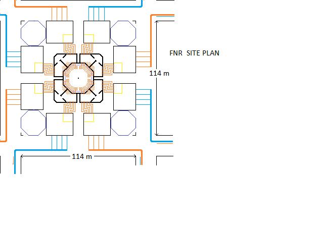
The sodium pool enclosure is in the middle of the FNR Site Plan shown below.
The cylindrical inner structural concrete wall supports the induction pumps and steam generators, supports the FNR dome and its loads, supports the NaK pipes, absorbs above pool level gamma emissions from Na-24 and forms the inner wall of the heat exchange galleries. The inside surface of this concrete wall is coated with a rubber like sealing material which has the effect of preventing unplanned gas exchange between the access space and the outside.
Immediately inside this concrete wall is a 1.2 m wide access space which provides an air flow path for closed circuit reactor leakage heat removal. Below the pool deck this space is > 3.5 m wide. This space can contain sodium pool wall lateral stabilization to prevent sodium pool damage during a very severe earthquake.
THERMAL WALL:
The thermal wall (shown in faint purple) is a 1.4 m thick layer of rigid fiber-frax insulation covered on both the inside and outside by gas tight sheet steel. The wall contains both hot and cold side structural members (steel I beam wall studs) that are supported so that the hot wall can flex inward about 16 cm relative to allow thermal expansion and contraction of the sodium pool structure and the NaK pipes passing through the wall. The hot wall surface moves radially with the pipes. The cold wall surface is sheet steel spot welded to the outer flange of the cold wall studs. The hot wall surface is sheet steel with vertical surface wave fronts, spot welded to the inner flange of the hot wall studs. The hot wall is also attached to the pool deck and hence its bottom moves with the pool deck. That movement is both radial and vertical.
The hot wall must be gas tight to contain both hot argon and sodium vapor in the pool space. The thermal wall is filled with argon gas at a positive pressure of about 4 inches WC to ensure overcoming a maximum sodium vapor pressure of about 3.6 inches WC. The cold wall must be gas tight to contain this pressurized argon. Absent that internal argon pressure the hot sodium vapor will attack the fiberfrax insulation if it leaks through small defects in the hot wall.
The cool wall is attached to the inner structural wall. That firm attachment is necesary to balance the thermal wall internal argon pressure. The bellows fitting connecting the hot wall to the pipe must accommodate thie combined relative movement. This fitting must also accommodate the vertical movement of the pipe axis relative to the hot wall.
A ducted argon gas blower keeps the argon pressure inside the fiberfrax containment cavity 4 inches of water above atmospheric pressure to prevent sodium vapor leaking into the fiberfrax. If this argon leaks into the 1 m wide cooled access space this leak is easily located by soap bubble testing. The intake to the argon gas blower has a gas cooler that condenses sodium vapor to prevent sodium vapor entering the thermal wall cavity via the argon pump inlet which is open to the pool space.
The outer sheet metal wall covering must be continuously edge sealed and bubble tested to be gas tight.
This connection must flex to allow thermal expansion and contraction of the NaK pipes connecting the intermediate heat exchange bundles immersed in the sodium pool to the steam generators located in the heat exchange galleries.
The wall space containing the fiberfrax ceramic insulation contains argon at 4 inches of WC above atmospheric pressure. The hot wall is used to contain the neutron activated sodium vapor within the sodium pool space. The cool wall is used to contain the positive pressure argon and exclude air. The hot wall normally operates at about 460 deg C to 500 deg C and the cool wall normally operates near ambient temperature.
The argon pressure inside the fiberfrax will tend to drive the hot and cool stainless steel walls apart. The cool wall has its own I beam studs to which the cool wall sheets are spot welded. The cool wall stud flanges are firmly connected to the inner structural wall to balance the argon pressure force that tends to separate the hot and cold walls.
Any small leaks of argon into the 1.2 m wide access space are located by soap bubble testing. These leaks are fixed by allowing the argon pressure inside the thermal wall to temporarily fall to atmospheric and then by applying sealing goop to the access space side of the cool wall wherever needed. The use of this sealing material must be limited because it will tend to increase the thermal resistivity for thermal wall leakage heat conducting into the 1.2 m wide access space.
Note that we need ongoing argon separation to purge air from inside the thermal wall.
The gas in the access space is circulated through a dome mounted closed loop refrigeration system which constantly dumps the leakage heat to outside air. A major benefit of this closed access space is that it protects the thermal wall from differential pressure damage in a tornado.
In normal reactor operation there should be no argon in the 1 m wide access space. The presence of any argon in the access space indicates a cool wall or bladder leak. Locating the vicinity of that leak requires scanning the cool wall of the 1 m wide access space with a mass spectrometer tuned to argon detection. Once the general vicinity of the leak has been detected the exact location can be found with a bubble test. A small controlled amount of outside air circulation may be admitted into the 1 m wide access space to gradually expel leakage argon and to provide a breathable atmosphere for persons working inside the access space.
Personnel access to the access space is via a double door airlock similar to the airlocks used on many commercial buildings.
Both the inner and outer steel coverings of the thermal wall must be able to sustain the small differential pressure. The fibrefrax between these coverings consists of three staggered layers so that heat leakage at fiberfrax board joints is minimal. The staggered fiberfrax boards must be fastened together with recessed staggered metal hardware. The exact interior layout of the screws forming this wall needs to be resolved.
Note that any argon which migrates from the pool space into the access space may bring with it small amounts of Kr-85 or Na-24. The Na-24 vapor will decay with a half life of 15 hours. This issue needs more study. If too much radioactivity is present the access space may need to be vented before any personnel enter.
The pool deck is slightly sloped toward the pool so that under normal circumstances sodium vapor condensation on the hot walls and NaK pipes drains back into the sodium pool. At the edge of the sodium pool there is a safety rail to prevent a suited worker accidentally slipping into the sodium pool.
Radiating out from the edge of the sodium pool are 96 NaK pipes, each 16 inch OD that connect the intermediate heat exchange bundles to the equipment in the adjacent heat exchange galleries. The 48 intermediate heat exchange bundles may be partially supported by chains fastened high up the hot wall and by axial force along the NaK pipes. These heat exchange bundles are free to move radially to allow for NaK pipe thermal expansion/contraction, and for limited movement for pipe flange alignment.
In the heat exchange galleries the pipes have a large S geometry to allow for thermal expansion of the steam generators.Note that the apparatus should be designed such that vertical thermal expansion of a steam generator is partially matched by vertical thermal expansion of the connected piping.
FNR POOL:
The sodium pool is a 20 m diameter X 15 m deep pool of liquid sodium with a normal top surface temperature of 460 degrees C. This pool is located on the central axis of the structural concrete enclosure. The sodium surface is 1 m below the level of the pool deck. Above the pool deck level is the themal wall which is 26 m inside diameter. The thermal ceiling lower surface is 10 m above the pool deck.
FNR ENCLOSURE HEIGHT COMPONENTS:
The main components of the FNR enclosure height are:
Baseplate thickness = ~ 2 m
Ventilation space under pool = 1 m
Supporting Fire brick = 2 m
Sodium depth = 15 m
Sodium surface to pool deck = 1 m
[Pool deck is 2 m above grade]
Baseplate's top surface depth below grade = 17.0 m
MINIMUM SAFE DEPTH OF WATER TABLE BELOW GRADE = 18 m
Pool deck to inner ceiling = 10 m
Ceiling insulation = 1 m
Service space = 1 m
horizontal girder height = 1 m_____
Dome = 8.5 m
DOME TOP HEIGHT ABOVE GRADE = 23.5 m
SODIUM POOL ENCLOSURE:
The sodium pool is mostly below grade. The top 2 m of the pool walls are above grade to prevent surface flood damage and to enable easy horizontal transfer of fuel bundles and intermediate heat exchange bundles via horizontal airlocks between the space over the sodium pool and flat deck truck mounted horizontal shielded fuel bundle shipping containers.
The pool deck is a 26 m diameter almost flat plate with the 20 m diameter sodium pool at its center. This plate fits 0.5 m under the fiberfrax filled side wall.
COVER GAS:
The enclosed space over the liquid sodium pool is filled with the inert gas argon which will not chemically react with either the liquid sodium or steel. The argon pressure is maintained at one atmosphere by argon filled bladders located in the access space under under the heat exchange galleries. This simple argon pressure control system does not require AC power. Fail safe argon pressure control is essential for sealed reactor enclosure structural integrity. As the bladders expand and contract access space air through the orifice between the service space and the outside to balance the air pressures.
FIRE PREVENTION:
If the reactor is shut down for an extended period the sodium surface should be flooded with kerosene to prevent sodium oxidation. However, that kerosene itself is a potential fire hazard and is difficult to remove. The number one objective is to keep oxygen out of the sodium pool space. Any oxygen that leaks into the pool space will gradually form Na2O which must be filtered out of the sodium. Any water vapor that leaks in will gradually form NaOH and H2. The NaOH must be filtered out. The hydrogen must be safely discharged to the outside with minimal loss of argon.
CONCRETE PURPOSE:
The concrete portion of the FNR enclosure normally remains at ambient temperature. The main function of the concrete is provide structural strength and to attenuate gamma radiation. Other functions of the concrete include:
1) Exclusion of ground water;
2) Exclusion of rain water;
3) Exclusion of flood water;
4) Protection from physical attack;
5) Reserve sodium containment;
6) Reserve fire containment;
7) Supporting the dome roof structure, the ceramic fiber insulated ceiling and the fuel bundle electronic monitoring equipment;
8) Guiding cooling air flow;
9) Resist tornados.
SHEET STEEL PURPOSE:
The functions of the hot wall sheet metal wall sheathing include:
1) Sodium vapor containment;
2) Argon containment;
3) Fiber-frax insulation protection.
The functions of the cool wall sheet metal sheathing include:
1) Air exclusion;
2) Argon containment;
3) Fiber-frax insulation physical protection.
Note that at points where the NaK pipes pass through the cool wall and the inner structural wall there are feed troughs filled with ceramic fiber for argon containment:
1) Matches the TCE of the pipe;
2) Is a good thermal insulator;
3) Remains gas tight over the temperature range 20 deg C to 530 deg C;
4) Is sufficiently soft as to not crack due to being hot near the centre while being cool near the outer perimeter.
The functions of the service spaces include:
1) Space sufficient for circulation of the cooling air flow;
2) Space for inspection and service access;
3) Clearance for thermal expansion.
4) Space for reactor control and monitoring equipment.
DOMED ROOF FUNCTIONS:
The primary function of the external domed roof is to provide physical protection against precipitation, violent storms (hurricanes and tornados) and aerial attack. The sodium pool enclosure must be gas tight and must dependably exclude both air and rain water under the most adverse circumstances.
The roof must also house forced air ventilation and cooling equipment, and must provide structural support for the ceiling, electronic monitoring system and NaCl fire suppresion.
The inner ceiling contains the 1 m of fiber frax insulation used to contain heat. The outer sheet metal covering of the fiber-frax contains the over pressure argon and provides secondary protection against a roof rain water leak. The inner sheet metal covering contains the fiber frax insulation and prevents penetration of the fiber frax by sodium vapor.
The innermost ceiling must be high enough (10 m above the pool deck) to allow fuel bundle and intermediate heat exchanger repositioning and replacement using the internal polar gantry crane.
Between the steel and concrete roof structure and the top of the inner ceiling is a 2 m high open space which allows easy access to the ceiling mounted reactor monitoring system and to the access space cooling equipment.
The weight of the roof assembly must be about 1500 tonnes to provide sufficient protection against tornado damage..
DEFENSE AGAINST A POTENTIAL AERIAL ATTACK:
The reactor enclosure domed roof must be strong enough to safely absorb a credible aircraft, bomb or missile impact. The roof must have a steel content comparable to a major highway overpass. The sandbag layers are below the roof surface and are high enough above the reactor monitoring equipment to allow the sandbags and roof structure to safely absorb most of the kinetic energy contained in a diving aircraft, bomb or missle. The sandbags operate by both dissipating projectile kinetic energy and by distributing impact momentum over a wide area.
If an imminent airborne threat to the FNR is detected the moveable fuel bundles should be withdrawn forcing a reactor cool shut down. To the extent that time permits sufficient heat should be extracted from the liquid sodium pool to prevent spontaneous combustion of sodium with air if there is a subsequent major roof failure.
If at any time a significant amount of air leaks into the argon cover gas the immediate requirement is to withdraw the movable fuel bundles to take the reactor to a cold shutdown and to lower the liquid sodium temperature below 200 C to prevent spontaneous sodium combustion in air. That rapid cooling is achieved by:
a) Using NaK to bring the Na temperaturde down to under 300 deg C.;
b) Using NaK to bring the sodium down to about 120 deg C.
The NaK temperature will drop to about 110 degrees C which will soon pull the sodium temperature down to about 120 degrees C.
The robust concrete and steel structure of the heat exchange galleries located around the FNR enclosure perimeter and the related shear walls make the FNR enclosure very resistant to a low angle physical airborne attack against its sides. Within a few seconds of an alarm the NaK in selected heat exchange galleries can drain down into below grade dump tanks with argon cover to rapidly extinguish almost any NaK fire.
FNR ENCLOSURE ROOF STRUCTURE:
The sodium pool enclosure roof is an octagonal structural steel dome. The roof design is constrained by the use of prefabricated structural steel members that are limited by road and rail transportation constraints to < 15.8 m in length. This objective can be achieved by use of domed roof.
Protecting the FNR sodium pool against a direct overhead air attack requires a roof structure which safely stops falling projectiles. The object of the sandbag layers and NaCl is to absorb and dissipate part of the projectile kinetic energy if the projectile penetrates the roof. Any projectile explosion should be forced to occur outside the roof dome so that the explosive shock wave is distributed over a wide area.
In an emergency a steel ball and NaCl cover can be maintained over the liquid sodium pool while a temporary new roof patch is applied. In such circumstances the liquid sodium pool should be cooled below 140 degrees C and then covered with a kerosene to prevent sodium combustion with air. Circumstances that might lead to such a roof failure include a direct overhead impact by an armour penetrating bomb, missle or meteorite. In these circumstances it is critical that the heat transport loops continue operating. They must all be independently powered.
There should be a sufficiently large supply of stored argon on-site to prevent sodium combustion while the liquid sodium temperature is being reduced following a sudden major roof failure.
There should be stock of thin sheet metal roof patch material stored in the roof space together with appropriate tools and supplies sufficient for temporarily blocking of any hole in the ceiling caused by a penetrating missle. In order to execute this fix the gamma radiation in the roof space from Na-24 in the sodium pool must be quantified. There may need to be a shielded access route for accessing the reactor monitoring system and roof space mounted ventilation equipment.
A 300 MWe FNR has 48 fully independent heat removal circuits connected to four independent district heating-cooling loops and 16 independent cooling towers. This level of independence provides certainty against loss of fission product decay cooling.
INNER AND OUTER CEILINGS:
The reactor enclosure inner ceiling will have an inside height above the pool deck of 10 m. The gantry crane I beam is supported by dollys running on two circular tracks which are in turn supported by the bird cage. The circular track is composed of multiple pieces.
The transverse I beam rail is 25.8 m long. This transverse I beam rail may need to be fabricated by field joining of two shorter I beam lengths. Alternatively the transverse I beam rail may have to be delivered by helicopter due to its 25.8 m length.
There are further complications related to mounting the monitoring electronics package. The monitoring system has four overlapping quadrents so as to see past the polar gantry crane transverse rail. Each electronics package will consist of two parts, one which illuminates the fuel bundle indicator tubes and one which receives and processes return data from these indicator tubes. The monitoring system electronics will require continuous cooling. Loss of this cooling must immediately trigger a reactor cool shutdown.
The inner ceiling sheathing over the sodium pool should be supported by hangers attached to the the outer ceiling sheathing and outer structural roof via thermal breaks. The inner ceiling sheathing is made from sheet steel and normally operates at about 460 degrees C. On top of the inner ceiling sheathing is a 1 m thick layer of high temperature rated fiber ceramic insulation so that the access space between the outer metal ceiling sheathing and the structural roof is cool. This space is normally kept cool by the mechanical cooling system.
SAFE ACCESS TO ROOF SPACE:
Safe access to the inside roof structure is contingent upon the design weight of sand or NaCl being present to absorb gamma emission from decay of Na-24. Provision should be made for safe servicing of the ceiling mounted electronics package.
Each monitoring electroncs package can be mounted on a radial track which moves it from a shielded area to near the center of the ceiling over the sodium pool. The worst case level of Na-24 gamma radiation in the ceiling space needs to be identified.
POLAR GANTRY CRANE:
The polar gantry crane must work reliably after being stored in the 460 degree C sodium vapor environment for an extended period of time. Temperature and sodium vapor sensitive components must be removed when the gantry crane is not in use.
The roof structure supports three rings of hangers with thermal breaks (ceramic egg insulators) that in turn stabilize the interior walls, interior ceiling ceiling.
The gantry crane transverse beam is rotated by worm gear drives located at the transverse beam ends. The transverse beam support wheels run on a circular track. There is a central pin to fix the axis of rotation. The dolly, winch and and hook assembly moves back and forth along the bottom of the transverse beam. The drive motors are removed for cool storage via top of side wall access ports when the gantry crane is not in use.
The gantry crane is only used when the liquid sodium pool is relatively cool (120 degrees C). Normally, when the reactor is operating, the remote manipulator is kept in cool storage. The detail of the connection methodology between the gantry crane remote manipulator and the gantry crane trolley remains to be resolved. This remote manipulator must be able to precisely place fuel bundles in their sockets and attach fixed fuel bundle corners together 6 m below the liquid sodium surface.
LIQUID SODIUM CONTAINMENT:
There is an inner steel cup, a middle steel cup and an outer steel cup. As long as at least one of these steel cups maintains its physical integrity the liquid sodium will be sufficiently contained to maintain its minimum required level for fission product decay heat removal following FNR shutdown. Between the steel cups is NaF and a small radial space to allow for differential thermal expansion of the steel cups. The pool deck is integral with the inner steel cup. The bottom of the pool deck, which extends under the enclosure walls around the sodium pool, has a 1 m thick layer of fiberfrax insulation.
Outside the outer steel cup are radial supports to the hot wall supporting I beams that reinforce the steel cups during severe earthquakes. These reinforcements also assist in outer cup assembly.
REACTOR FUEL:
During normal reactor operation there is no requirement for personnel to enter the argon filled pool enclosure. Such entry should only occur after the reactor has been in cold shut down for at least a week to allow Na-24 gamma emission and the pool temperature to subside. Even so such entry requires personal protectrive equipment against the ~ 120 degree C temperature and requires closed circuit breathing equipment.
The fuel bundles are centrally positioned in a 20 m diameter X 15 m deep liquid sodium pool. A 1.7 m wide band of liquid sodium at the perimeter of the liquid sodium pool is dedicated to intermediate heat exchangers and NaK pipes. The remaining sodium guard band serves as a corridor for movement of hot fuel bundles.
The central core region of the reactor together with the top and bottom blanket regions involve ~ 800_____vertical active fuel bundles. Each fuel bundle is 6.5 m high and has an additional 1.5 m bottom support pipe projection. Fixed fuel bundles are supported by 3 m high modules that in turn fit into feet resting on the bottom of the sodium pool. Each movable fuel bundle has a 1.5 m long bottom probe extension and a removeable 7.0 m high top indicator tube.
The movable fuel bundles slide into the fixed fuel bundle matrix from the bottom. The insertion distance is set by a liquid sodium hydraulic actuator with 1.1 m of travel. For each movable fuel bundle an indicator tube projects above the liquid sodium surface to indicate the movable fuel bundle's actual vertical position. This vertical position is constantly monitored using an overhead monitoring system that operates similar to a laser measuring tape.
The reactor core region is surrounded on its outer perimeter by a 1.20 m thick blanket formed from 4 rings of passive fuel bundles.
There are two further outer rings of used fuel bundles in which natural decay of fission products occurs over a six year period before the fuel bundles are removed from the liquid sodium pool. Thus the total effective blanket width is:
3 X 0.6 m = 1.8 m.
FISSION PRODUCT DECAY HEAT REMOVAL:
One of the most important aspects of fission reactor design is provision for fission product decay heat removal under adverse circumstances. If some event occurs which causes a reactor shutdown the fission products will for a short time continue to produce decay heat at up to 8% of the reactor's full power rating. It is essential that there be a 100% reliable means of ensuring ongoing removal of the fission product decay heat under adverse conditions such as shortly after a severe earthquake when station power may be lost.
To provide certainty regarding fission product decay heat removal a FNR has 48 independent heat transport loops. In the event of loss of station power fission product decay heat removal should be achieved by natural fluid circulation with just half of the heat transport circuits in service.
During normal reactor operation, for safety certainty at any instant in time, at least 2 of the 8 heat exchange galleries connected to two different cooling towers should be operational.
For a liquid sodium cooled FNR all heat removal is via liquid sodium and NaK, so it is essential that:
1) Under no circumstances will the liquid sodium level ever fall to the point that adequate fission product decay heat transfer to NaK via the intermediate heat exchangers is no longer possible.
2) The liquid sodium pool walls are designed such that if the inner and middle nested cup walls fail and the liquid sodium leaks into the space between the walls, the leakage into the space between the walls will not lower the liquid sodium level more than 4 m, so 2 m of intermediate heat exchange bundle tube length is still immersed in the sodium.
3) Even if the intermediate loop NaK induction pumps fail there is enough NaK natural circulation to ensure safe removal of the fission product decay heat.
4) The NaK dumps its heat into water/steam. In a heat dump situation the steam generator water side remains at atmospheric pressure so that the injection water pumps do not face a pressure load.
5) There must be enough clean water in on-site storage such that in an emergency the fission product decay heat can be removed by evaporating that water. In the winter the cooling towers normally operate dry with pumped steam condenser cooling water circulating through the heat exchange coils located near the bottom of the cooling tower. In the summer the towers can operate wet for additional heat rejection.
FUEL BUNDLE REPOSITIONING:
The fuel bundles are repositioned and/or replaced from time to time using the polar gantry crane and remote manipulation. Note that the ceiling height is sufficient to allow extraction and replacement of individual fuel bundles and individual intermediate heat exchange bundles. During the extraction process used fuel bundles are lifted sufficiently to clear the other bundles and then are then moved horizontally to the reactor perimeter zone of the sodium pool where the irradiated fuel bundles are stored until they lose most of their fission product decay heat before being removed from the sodium pool. The fuel bundles must be permitted to drip dry over the sodium pool before being moved into an airlock.
EARTHQUAKE PROTECTION:
The FNR fuel assembly can be thought of as being centrally located in a 15 m deep liquid sodium pool with a liquid sodium top surface which is 1 m below the pool deck.
In an earthquake with a 1.5 g horizontal component sustained liquid sodium surface waves might slosh right up to the ceiling. The sodium pool space inside walls must withstand the related forces.
In an earthquake the fuel assembly and concrete tends to stay in constant relative position while the liquid sodium pool will slosh about.
The interior cylindrical concrete walls surrounding the sodium pool are stabilized on the outside by the reinforced concrete shear walls forming the heat exchange galleries.
CHEMICAL THREATS:
The main chemical threat from a power FNR is the 4000 m^3 of liquid sodium contained in the sodium pool. If this liquid sodium contacts water there will be a rapid chemical reaction which liberates hydrogen that will spontaneously ignite in an air atmosphere. Hence one of the main issues in FNR application is choice of a reactor site where the sodium will NEVER be exposed to flood water. The reactor site is chosen such that the reactor foundation will always gravity drain.
Even if the foundation drain becomes blocked and the reactor enclosure floods 18 m deep the outer stainless steel wall around the sodium pool should prevent any contact between water and the sodium.
The other potential threat is a sodium fire. Quite apart from the release of Na2O and NaOH the big threat is melting of the fuel tubes leading to potential release of air borne TRU and fission products. It is essential that the reactor be designed and sited such that a large sustained sodium fire cannot occur. In order to extinguish a sodium fire the oxygen concentration over the sodium must be minimized and heat must be extracted from the sodium. That heat extraction requires reliable operation of at least a fraction of the NaK heat transport systems. Under no circumstances can water be allowed to contact either the sodium or the NaK.
The soil and bedrock outside the physical enclosure should be sufficiently dry, dense and stable to safely contain the liquid sodium in the extremely unlikely event that a major earthquake ruptures the hot wall, cool wall, structural wall and physical wall.
It is equally important that there be an effective non-water based fire suppression system. The local fire department must be trained that water should NEVER be used to fight a FNR fire. Inappropriate use of water carried by a fire truck could change a minor fire into a major disaster. The FNR has excess argon, buoyant steel balls and excess NaCl in silo storage for emergency use.
To mitigate the fire threat the liquid sodium is covered by argon cover gas, a sodium vapor resistant hot wall, a gas tight cool wall and a gas tight inner seal on the inner cylindrical structural concrete wall. In the event of air penetration into the sodium pool space the reactor should be immediately shut down and heat removed from the liquid sodium pool to lower the liquid sodium temperature below 200 degrees C so as to prevent spontaneous combustion of sodium in air. As the argon temperature over the sodium pool decreases stored argon from bladders is automatically added to the argon cover gas to maintain the 1 atmosphere pressure in the sodium pool space.
Once the liquid sodium temperature is below 140 degrees C the surface of the liquid sodium can be flooded with a thin layer of kerosene to prevent the liquid sodium oxidizing during prolonged work such as roof repair.
Similarly if there is an enclosure roof failure the immediate objective is to extract heat from the sodium to reduce its temperature to the point where kerosene can be safely used to prevent sodium oxidation. Until the heat is removed from the sodium argon must be used to exclude oxygen from the sodium surface. That heat extraction might easily take half an hour, depending on the available heat sinking capacity. The fastest way to emergency cool the system is to directly vent steam from the steam generators. It is important to have enough water in on-site tank storage to remove the fission product decay heat by latent heat of vaporization. Then the limiting factor is the maximum safe heat transfer capacity of the intermediate heat exchanger tube bundles and the steam generator tube bundles. If there is a FNR roof failure it is essential to prevent vented steam falling back into thesodium pool space.
The steam vents should go into the on-site cooling towers. This issue highlights the importance of FNR enclosure roof and ceiling integrity and immediate availability of material for temporary exclusion of rain or other water falling from overhead.This web page last updated June 3, 2026
| Home | Energy Physics | Nuclear Power | Electricity | Climate Change | Lighting Control | Contacts | Links |
|---|