| Home | Energy Physics | Nuclear Power | Electricity | Climate Change | Lighting Control | Contacts | Links |
|---|
INDUCTION PUMP:
The FNR is designed to operate with natural primary sodium circulation and with pumped secondary NaK circulation. The induction pumps are located on the return side of the NaK secondary loops. This configuration allows good thermal power control while minimizing the induction pumps' cumulative exposure to high temperatures and gamma radiation.
Each NaK induction pump must be sized to overcome the NaK flow induced pressure drop in the corresponding intermediate heat exchange bundle, the NaK piping, the steam generator and the induction pump itself. In addition there is a critical suction head limitation. Note that the induction pump must be physically as low as possible in the NaK loop to ensure a positive suction head.
An induction pump operates by inducing a circular current in the NaK cylinder around the induction pump torpedo. This current crosses a radial magnetic field component causing the NaK to experience an axial force. External 3 phase coils, analogous to the stator coils of a 3 phase AC motor, create a suitable distributed time varying magnetic field.
Changing the applied 3 phase AC frequency and amplitude changes the pumping rate.
NaK HEAD PRESSURE RATING:
The purpose of having a high NaK head pressure rating is to permit safe management of steam generator tube failures.
The NaK loop head pressure rating is set by the 18 inch OD 0.375 inch wall flow tube hoop stress rating. The outward acting force: P X L X 17.25 inch
The inward acting force = 2 L (.375 inch) 39 MPa
Hence:
P = 2 (.375 inch) 39 MPa / 17.25 inch = 1,695 MPa
~1.7 MPa
This working pressure limit determines many other NaK loop parameters.
The induction pump must dependably operate over the temperature range 15 degrees C to 500 degrees C. It should be hydraulic pressure tested at 2.55 MPa.
INDUCTION PUMP FUNCTION:
The induction pump is used to cause controlled variable NaK flow through the NaK loop.
Induction pumps for NaK are built using a stainless steel flow pipe. As compared to liquid NaK stainless steel has a relatively high electrical resistivity and is non-magnetic. In the middle of the induction pump flow pipe is the ferromagnetic core known as the "torpedo" made from transformer iron laminations. Due to the high torpedo operating temperature the laminations must be bound together by a glaze rather than by varnish.
An induction pump uses external AC solenoids to induce a circular currents in liquid NaK surrounding the torpedo shaped core. These currents interact with radial magnetic field components to cause an axial force on the liquid NaK in the annulus between the flow tube and the torpedo.
The FNR power is controlled by using the induction pump to modulate the NaK flow rate through the intermediate heat exchange bundle and the steam generator. The steam production rate is approximately proportional to the NaK flow rate and its change in temperature. In normal operation the loop change in temperature is about 120 degrees C implying that the normal NaK temperature at the induction pump is about 330 degrees C.
A major constraint on induction pump efficiency is the electrical conductivity of the surrounding stainless steel flow pipe wall. The pipe wall forms a parasitic current ring path which reduces the circulating current in the liquid NaK and hence reduces the pump efficiency.
In theory the efficiency of an induction pump could be substantially improved by using a flow pipe material with a higher electrical resistivity. However, with non-metal materials there are major problems in achieving dependable leak proof high temperature connections between the induction pump flow pipe and the connected extended steel pipes.
The induction pump will require custom made components. One of the fabrication issues is whether or not the torpedo can be inserted after the diameter reducing flow tube end pieces are fastened in place.
INDUCTION PUMP DESIGN:
A three phase annular linear induction pump is similar in concept to a linear induction motor. This design is complex to analyse theoretically but it offers the benefit of ability to work against a higher pump head, since its head capacity increases with the number of pump stages. This general pump design has been successfully used by others in relatively low pressure sodium cooled reactor applications.
The induction pump flow pipe material must dependably withstand the
1.7 MPa X 1.5 = 2.55 MPa
surge test pressure. In this respect a major issue is hoop stress tolerance at 460 degrees C.
The proposed three phase annular linear induction pump design involves a 18 inch OD,0.375 inch wall stainless steel induction pump flow tube with 16 inch diameter to 18 inch adapters at both ends. There is a slight potential problem with incomplete drainage of NaK from the induction pump.
The induction pump internal torpedo is 14 inch OD. Outside the flow tube and separated by a thermal break there are a series of three phase coils along the flow tube length separated by washer like laminated iron sections with IDs of slightly over 18 inches. Each magnetic gap is about 2.125 inches (0.125 inch thermal break + 0.375 inch stainless steel + 1.625 inch of NaK). Each laminated iron washer thickness is about 6 inches thick, 18.2 inch ID, 30 inch OD. Each coil length is about 6 inches. Each coil is about 18.2 inch ID, 30 inches OD.
There is a cylindrical surround about 36 inch OD X 30 inch ID X 4.5 m long again made from laminated iron to complete the magnetic circuits. The coils are cooled by circulating oil jacket 3 inches thick on top of which there are 3 inches of insulation which gives an OD of 48 inches.
Thus each 3 phase pumping section is 3 (6 inch + 6 inch) = 36 inch long.
Four such pumping sections are:
(4 X 36) + 6 = 150 inches long = 3.81 m
The drawing shows the availability of 3.6 m.
Hence the end fitting lengths need slight adjustment.
The volume of NaK around the induction pump torpedo is:
Pi [(8.625 inch^2 - (7.0 inch)^2)] [3.6 m] [(0.0254 m / inch)^2]
= 0.1853 m^3
At the induction pump inlet the 16 inch to 18 inch adapter must fit within the available space.
At the induction pump discharge the 18 inch X 16 inch reducing fitting and the 16 inch X 16 inch X 16 inch Tee must fit within the available space.
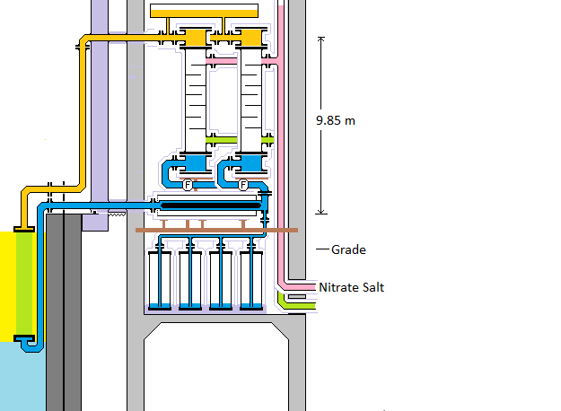
SPACE CONSTRAINT:
The induction pump positioning is shown on the following diagram.
The maximum available length for the induction pump flow tube is 3.6 m.
INDUCTION PUMP SUCTION PRESSURE CONSTRAINT
A significant issue that constrains the heat transport system design is the induction pump suction pressure requirement.
The NaK piping external to the induction pump is nominally 16 inch OD. Inside the induction pump is a magnetic torpedo which causes the NaK flow to be annular. The inside radius of the flow annulus is 7.0 inch. The outside radius of the flow annulus is:
(9 inch - 0.375 inch) / 2 = 8.625 inch.
The cross sectional area of the flow annulus is:
Pi (R2^2 - R1^2) = Pi [(8.625 in)^2 - (7.0 inch)^2]
= 3.14(74.39 - 49) in^2
= 79.72 in^2
= 0.0514 m^2
The 16 inch pipe cross sectional open area is:
Pi [8 - .375) / 2)^2 inch^2 = 182.56 inch^2
Hence in the annulus the NaK axial flow velocity must increase by a factor of:
(182.56 / 79.72) = 2.29
The induction pump suction pressure requirement is the pressure required to accelerate the NaK from stationary to the required annulus flow rate.
The NaK has a density of about:
Rho = 1.1 X 10^3 kg / m^3.
From FNR NaK Loop the required volumetic NaK flow rate is about 0.185 m^3 / s.
The corresponding annulus flow velocity is:
(0.185 m^3 / s) / (0.0514 m^2) = 3.56 m / s
The kinetic energy / second of the flowing NaK past a certain point is:
(volume / second) X (mass / unit volume) X (kinetic energy / unit mass) = (Fv Rho) V^2 / 2 = A V Rho V^2 / 2
Kinetic energy supplied / unit time = Force X distance /time = Force X velocity = delta pressure X A X V
Equating these two terms gives:
Delta pressure = Rho V^2 / 2
= 970 kg / m^3 X (3.56 m / s)^2 / 2 = 6147 Pa
INDUCTION PUMP MASS
The induction pumps contain a lot of iron and hence are really heavy.
The torpedo is
Pi (7 inch)^2 X 4.65 m X 7.6 X 10^3 kg / m^3 X (,0254 m / inch)^2 =______
The annulus is:
Pi [(8.625 inch)^2 -(7.0 inch)^2] X 4.65 m X 1000 kg / m^3 X (.0254 m / inch)^2 = ___
The flow tube is:
Pi[(9.0 inch)^2 - (8.625 inch)^2] X 4.65 m X 7.6 X 10^3 kg / m^3 X (.0254 m / inch)^2 = _____
The washers are:
Pi[(15 inch)^2 - (9.11 inch)^2] X (4.65 m / 2) X 7.6 X 10^3 kg / m^3 X (.0254 m /inch)^2 = ___
The windings are:
Pi[(15 inch)^2 - (.1 inch)^2] X (4.65 m / 2) X 3 kg / m^3 X (.0254 m / inch)^2 = ______
The surround is:
Pi [(18 inch)^2 - (15 inch)^2 X 4.65 m X 7.6 kg / m^3 X (.0254 m/ inch)^2 = ____
The oil jacket is:
Pi [(21 inch)^2 - (18 inch)^2]X 4.65 m X 1000 kg / m^3 X .0254 m / inch)^2 = ____
Total induction pump mass = _______
INDUCTION PUMP SUPPORT:
A non-trivial issue is the weight of the induction pumps. These pumps must be supported by I beams so that the pump weight is not transferred onto the feed pipes or other equipment. Note that this support must not block the pipe to the dump tank. The support also must be consistent with the induction pump's external thermal insulation.
SUPPORT BEAMS:
Each induction pump and steam generator rests on two dedicated support cross I beams. These beams between the two walls bear the weight of the induction pumps and the steam generators. The dump tanks should be located underneath the induction pumps. When insulated these dump tanks are 1.5 m diameter.
Hence the induction pump requires serious design optimization to reduce its weight.
The induction pump flow pipe materials must be engineered to dependably withstand the 2.65 MPa hydraulic test pressure. In this respect a major issue is hoop stress tolerance at 390 degrees C.
INDUCTION PUMP INEFFICIENCY:
The wall of the 18 inch OD stainless steel flow pipe forms a single turn around the laminated iron torpedo which converts much of the applied electrical energy into heat. Part of the applied electrical energy forms circulating current in the liquid NaK. The interaction of that circulating current with the radial magnetic field in the magnetic gaps accelerates the liquid NaK. Most of the heat generated is absorbed by the liquid sodium. However, conducted heat and energy dissipated in the external laminated iron must be absorbed by the pumped oil coolant.
Electrical Resistivities:
Na = 47.7 X 10^-9 ohm-m @20 deg C
K = 72 X 10^-9 ohm-m @ 20 deg C
Stainless steel = _______
The induction pumps form a considerable parasitic electrical load on the FNR. A significant effort should be applied to maximize induction pump efficiency.
This web page last updated March 7, 2026
| Home | Energy Physics | Nuclear Power | Electricity | Climate Change | Lighting Control | Contacts | Links |
|---|