FAST NEUTRON REACTOR (FNR) INTRODUCTION:
This web page provides a broad overview of liquid sodium cooled Fast Neutron Reactor (FNR) technology. For detail on any particular aspect of that technology the reader is referred to the nuclear power section at www.xylenepower.com.
Fast Neutron Reactor (FNR) technology is the only proven means of supplying clean, firm and fuel sustainable electrical and thermal power that can fully displace fossil fuels. Properly designed FNRs and related fuel reprocessing also eliminate both long lived solid nuclear fuel waste and decommissioning waste. If humans are to continue to inhabit planet Earth, FNR technology must be adopted for fossil fuel displacement.
In principle a fuel sustainable FNR, in combination with appropriate periodic fuel reprocessing, provides about 200X the natural uranium fuel utilization efficiency of a Light Water Reactor (LWR) and about 100X the natural uranium fuel utilization efficiency of a CANDU reactor.
The power reactors described herein are cooled with low pressure liquid sodium, which enables safe installation at urban sites. Each such nuclear power plant (NPP) is rated to supply up to 300 MWe of electricity and 700 MWt of low grade heat, or up to 1000 MWt of high grade heat (10 MPa steam at more than 400 degrees C).
The construction support requirements for a 300 MWe FNR, in terms of site offices, storage space, cranes, access roads, parking, etc., are comparable to the construction of a multi-tower high rise condominium development.
Low operating pressures, triple nested enclosures and a multiplicity of independent heat transport loops enable the use of conventional industrial piping for fluid heat transport instead of requiring nuclear qualified heat transport materials, as in most water cooled reactors.
Achieving fuel sustainability requires a high neutron utilization efficiency, which is difficult to realize with a very small reactor. The compromise reactor size of 300 MWe is sufficient for fuel breeding while avoiding large reactor challenges including: difficulty siting, difficulty financing, difficulty integrating into smaller electricity grids and difficulty interfacing with district heating.
FNRs also lend themselves to electricity generation at sites where there is insufficient low cost water for evaporative cooling, so that the only practical heat sinks are dry cooling towers.
Due to use of sodium coolant, for fire safety FNRs must always be located at elevations sufficient to ensure that the reactor sodium pool will never be flooded with water.
Capital cost is minimized if the reactor foundation can rest on contiguous near surface igneous bedrock.
A major difference between water cooled reactors and sodium cooled reactors lies in provisions for repair and maintenance. When water is subject to a neutron flux it produces various isotopes with half lives of less tnan 30 seconds. Hence, if maintenance is required on a water cooled reactor, radiation from the coolant will decrease about one million fold in about 10 minutes.
However, when sodium coolant is exposed to a neutron flux it produces Na-24 that has a half life of about 15 hours. It takes about two weeks for the Na-24 radiation to decrease one million fold. Hence, a major issue with sodium cooled reactors is design of the heat transport system such that most repair and maintenance can be done without a reactor shutdown. The heat transport system of a sodium cooled FNR should consist of many (48) parallel independent heat transport loops configured such that a defective loop can be shut down with minimal negative impact on overall NPP performance. The defective loop can either be repaired or left shutdown until the next scheduled reactor fuel change. This operating and maintenance strategy greatly increases the capacity factor of a sodium cooled reactor.
FNR FUEL CYCLES:
Trans Uranium Actinides (TRU) are the mixture of atoms with atomic numbers greater than 92 that is formed when low kinetic energy (thermal) neutrons are absorbed by nuclei of the abundant uranium isotope U-238. Typically about half of TRU is Pu-239. In a FNR core zone, where fissioning causes a flux of high kinetic energy (1 MeV to 2 MeV) neutrons, TRU atoms interacting with fast neutrons will preferentially fission.
A fuel sustainable FNR has a U-238 blanket zone surrounding the core zone that, together with the core zone, converts the abundant fertile fuel U-238 into fissile TRU faster than the FNR core zone fissions the TRU. Hence there is net TRU production.
The TRU based FNR core fuel required for FNR startup can be obtained by reprocessing used CANDU reactor fuel. Most of the reprocessing residue becomes FNR blanket fuel. At about 6 year intervals there is a scheduled FNR shutdown during which time 20% of the used fuel bundles are replaced by recently reprocessed fuel bundles and the remaining fuel bundles are repositioned to maximize reactor performance while minimizing chemical reprocessing.
A FNR eliminates long lived radio active TRU by repeatedly exposing the TRU atoms to a fast neutron flux until these TRU atoms fission into stable lower atomic number atoms and radio isotopes with relatively short half lives.
There is another fuel sustainable FNR fuel cycle that theoretically can convert the abundant fertile fuel Th-232 into the fissile fuel U-233 faster than the FNR fissions U-233. However, there are multiple practical implementation challenges with deployment of the Th-232 fuel cycle, so this web site focuses on FNRs based on the U-238 fuel cycle.
SODIUM COOLED FNRs:
Sodium cooled fast neutron reactors (FNRs) of various sizes ranging from 20 MWe to over 800 MWe have been built and operated in Russia, USA, France and China. Several FNRs have operated continuously for more than 30 years. Major advantages of sodium cooled FNRs over other potentially sustainable nuclear power technologies are that sodium cooled FNRs can be constructed using readily available materials and all the related performance and long term material degradation issues have been resolved. Large scale deployment of sodium cooled FNRs is primarily a matter of political will.
A Fast Neutron Reactor (FNR) fissions with fast neutrons, as distinct from a water moderated reactor which fissions with slow (thermal) neutrons. A FNR fuel bundle cannot be directly water cooled because the hydrogen atoms in water would moderate (slow down) neutrons too quickly. Sodium nuclei are about 23X more massive than neutrons and hydrogen nuclei.
A sodium cooled FNR is superficially simple and extremely reliable. It consists of a pool of liquid sodium, which contains an assembly of immersed vertical sealed chrome-steel tubes containing metallic nuclear fuel. FNRs are designed to maintain a nearly constant sodium surface temperature, typically about 460 degrees C, independent of the thermal load. When heat is extracted from the sodium pool the core zone reactivity adjusts to keep the sodium pool discharge temperature fixed at 460 degrees C.
FNR SAFETY:
A FNR passively maintains a fixed liquid sodium temperature via a reactivity that decreases with increasing temperature. At the setpoint temperature the reactivity is zero. For safety a FNR must exhibit a negative slope reactivity versus temperature characteristic under all credible circumstances.
The reactivity versus temperature characteristic is partially the result of concentrated TRU in the core fuel. The TRU is typically at least half plutonium. Plutonium has an exceptionally large thermal coefficient of expansion (TCE).
The FNR design must also prevent sudden unplanned drops in the liquid sodium coolant inlet temperature to the fuel assembly, which might potentially cause fuel rod centerline melting.
The Soviet Union also made lead-bismuth eutectic cooled FNRs for submarine propulsion. This author rejects use of lead-bismuth eutectic for power production because in a neutron flux it produces the extremely dangerous polonium isotope Po-210.
FUEL SUSTAINABILITY OF FAST NEUTRON REACTORS (FNRs):
Fuel sustainable FNRs are far more fuel efficient than water moderated nuclear reactors because, per unit of energy production, fuel sustainable FNRs consume about 100X less natural uranium and produce about 1000X less long lived nuclear waste than CANDU reactors. FNRs also have physical safety features which allow them to be safely sited inside major cities where they can supply both electricity and district heat.
A 300 MWe FNR fuel assembly consists of about 536,000 X (3 / 8) inch OD vertical chrome steel fuel tubes, where each fuel tube contains a 4.2 m high stack of fuel rods. In the core fuel tubes, about half way up each fuel rod stack is a 0.6 m long core fuel rod. Above and below this core fuel rod are 6 X 0.30 m high blanket fuel rod stacks. At the core fuel rod level horizontally there are four concentric zones. The inner zone, referred to as the "core zone" is 10.4 m in diameter and is composed of 16 concentric rings of fuel bundles containing concentrated TRU plus U-238. The next zone, referred to as the "blanket zone" has an outside diameter of 12.8 m and is composed of 4 concentric rings of fuel bundles containing U-238. The third zone, referred to as the "cooling zone", has an outside diameter of 14.0 m and consists of 2 concentric rings of used core zone fuel bundles. The fourth zone, which contains the guard band and the immersed intermediate heat exchange bundles, has an outside diameter of 20 m, an inside diameter of 14 m and contains no fuel bundles.
Adjacent to the sodium pool wall and closer to the liquid sodium surface is a 2 m wide ring of intermediate heat exchange bundles containing pump circulated NaK that extracts heat from the hot liquid sodium. The blanket zone, cooling zone and guard band protect the intermediate heat exchange bundles and the inner wall of the sodium pool from neutron impingement. The guard band also provides for radial NaK pipe and radial fuel assembly thermal expansion, provides for earthquake induced movement of the fuel assembly with respect to the intermediate heat exchange bundles and sodium pool walls and provides a path for repositioning of hot fuel bundles while keeping them immersed in liquid sodium.
FNRs fission TRU primarily in the core zone. Excess fission neutrons that are not required to maintain the fission chain reaction and the breeding reaction in the core zone diffuse radially and vertically into the blanket zone where they lose kinetic energy and cause further transmutation of blanket U-238 into TRU.
Any neutrons that are absorbed by U-238 in the cooling zone form TRU that can be later recovered during used core fuel reprocessing. The thermal emission due to fission in the cooling zone is believed to be inconsequentially small.
Any neutrons that escape from the blanket zone or cooling zone are absorbed by sodium in the 3 m thick guard band where these neutrons convert Na-23 into Na-24, which beta decays with a 15 hour half life into stable Mg-24. There is an option of adding a gadolinium skirt around the outer perimeter of the cooling zone to further attenuate the neutron flux incident on the intermediate heat exchange bundles.
At about six year intervals fuel bundles that are in the cooling zone are removed from the sodium pool for reprocessing and the oldest (1 / 5) of the hot radioactive core fuel bundles are moved from the core zone to the cooling zone. Simultaneously the interior ring (1 / 5) of the blanket fuel bundles are also removed from the sodium pool for reprocessing. Reprocessing rejects fission products and separates the remaining TRU and U-238 for recycling.
The remaining core fuel bundles are move radially inwards and the removed core fuel bundles are replaced by new core fuel bundles fabricated from recycled TRU and recycled U-238.
The removed interior ring of blanket fuel bundles is replaced by the 2nd to interior ring blanket fuel bundles.
The remaining two rings of blanket fuel bundles each step one ring position towards the fuel assembly center.
The now vacant blanket fuel bundle outer ring is filled with new blanket fuel bundles formed from fuel rods mainly consisting of 90% new U-238 plus 10% Zr.
This fuel cycle can keep repeating as long as there is a supply of new U-238 to feed the outer layer of the blanket. Typically, after five such cycles, about 15% of the core fuel mass has fissioned and all of the fuel bundles have been reprocessed once.
The required amount of electrochemical reprocessing is minimized by mechanical recycling of blanket fuel rods located near the top and bottom of of each fuel rod stack. When the contents of a fuel tube are recycled the innermost blanket fuel rods are electrochemically reprocessed and the remaining blanket fuel rods all move one position closer to the core fuel. For economy the process of loading fuel tubes with appropriate fuel rods in the correct order must be fully automated, as must fuel bundle fabrication. Each reactor contains 1461 fuel bundles of which 20% are exchanged every 6 years.
At each fuel cycle the fuel reprocessing yields an excess of TRU which can be used to start other FNRs.
The recycled TRU contains about (1 / 2) Pu-239 and about (1 / 6) Pu-240. This plutonium isotope mix is unsuitable for nuclear weapon use due to too high a fraction of Pu-240. Separating the Pu-240 from the Pu-239 is extremely difficult and is well beyond the capacity of rogue parties. It is quite difficult and time consuming to form military grade pure Pu-239 with this type of reactor due to the two week long shutdown time required to execute fuel bundle configuration changes.
Those parties who oppose fuel sustainable FNRs due to imaginary fear of rogue access to pure Pu-239 are in effect choosing certain thermal extinction of mankind by forcing continuing use of fossil fuels.
FNR ADVANTAGES:
For stationary electricity and heat production FNRs have major practical advantages over existing water cooled reactors including:
a) Extreme simplicity enabling autonomous operation;
b) Small footprint for urban siting;
c) A 100 fold to 200 fold improvement in natural uranium utilization efficiency;
d) A 1000 fold reduction in long lived solid nuclear waste production;
e) Fuel sustainability by production of more fissile TRU atoms than the FNR consumes enabling FNR fleet growth;
f) Low pressure sodium coolant pool and NaK heat transport fluid loops which enable safe urban reactor siting;
g) Production of higher temperature and drier steam than a light water reactor increasing efficiency of electricity generation and decreasing steam turbine wear;
h) Temperatures of up to 450 degrees C available for industrial material processing;
i) Ability to deliver commercial steam at full load at up to about 400 degrees C.
j) Ability to rapidly change electricity output for electricity grid stabilization.
FNR DISADVANTAGES:
A FNR contains no low atomic weight elements such as hydrogen or carbon to moderate its neutrons. A consequence of the resulting high neutron speed is that the neutron fission cross section in a FNR is substantially less than in a thermal neutron reactor, so to maintain a chain reaction the required fissile fuel atom inventory must be much larger than in a thermal neutron reactor of similar rated power.
The coolant sodium is incompatible with water, so for public safety a FNR must be sited where it will never be subject to flooding by water. This site constraint may imply that any waste heat from electricity generation that is not used for district heating must be rejected via cooling towers instead of via direct lake or sea water cooling.
New FNR fuel bundles contain recycled nuclear fuel which may be intensely radioactive. Hence FNR fueling is done via remote manipulation using shielded fuel bundle transport containers and a polar gantry crane.
After operation A FNR's sodium coolant contains Na-24 which has a half live of about 15 hours. Hence, to realize a high capacity factor, a FNR's heat transport system must allow safe repair and maintenance while the reactor remains in service.
REFERENCES:
An industry bench mark FNR design is the Ge-Hitachi PRISM.
PRISM Technical Paper
Another industry benchmark in both FNR design and performance was the EBR-2 as described inthe text "Plentiful Energy" by Til and Chang.
FAST NEUTRON REACTOR SIDE ELEVATION:
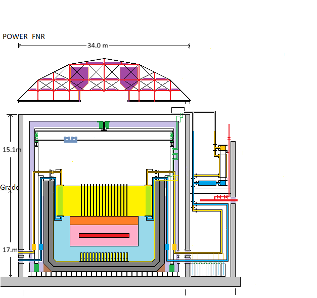
For diagramatic simplicity, the air locks and the open steel lattice supporting the fuel bundles are not shown.
Only 1 of 48 identical heat transfer loops, wrapping around the FNR perimeter, is fully detailed.
Color Code:
Red - Reactor Core, Steam Main
Pink - Reactor Blanket
Orange- Fuel Tube Plenum
Gold- Warmer NaK pipe
Yellow- hot sodium, hydraulic sodium tube, hydraulic lifter
Light Green - Intermediate Heat Exchange tubes
Dark Green - Hot wall thermal brake support, polar gantry bearings,
Light Purple - Fiber Ceramic Insulation
Dark Purple - NaCl Reservoir
Light Blue- cool sodium
Dark Blue - Cooler NaK Pipe
Light Gray - Concrete
Dark Gray - Fire Brick
Black - Steel Outline
FUEL SUSTAINABLE FNR OPERATION:
A fuel sustainable FNR consists of a central core of fissile reactor fuel (core zone) which is surrounded by six layers of fertile blanket fuel (blanket zone + cooling zone), which in turn are surrounded by a thick layer of sodium coolant which acts as a neutron absorbing guard band. Heat is removed by coolant flowing upward through narrow vertical channels that pass through the entire fuel assembly. This coolant then flows downward past the intermediate heat exchange bundles that are located close to the sodium pool walls.
The central core zone operates as a fission reactor which emits heat to the coolant. Surplus neutrons from the fission process diffuse out radially from the core zone and are absorbed by the surrounding layers of blanket fuel. Each successive layer of blanket fuel reduces the radial neutron flux by about a factor of two. Thus at the outside of the cooling zone the radial neutron flux is reduced by about a factor of 64.
In the blanket fuel each absorption of a neutron produces a new TRU atom at that location. Thus, after a few years of operation the concentration of TRU atoms in the innermost blanket fuel layer is maximum.
Every few years the reactor is shut down. A portion of the core fuel and the innermost layer of the blanket fuel are removed and are electrochemically reprocessed. Low atomic weight fission product atoms are extracted from the core fuel and sent to 300 year storage for natural decay. The low atomic weight atoms removed from the reprocessed core fuel are replaced by new high atomic weight TRU atoms extracted from the innermost layer of the blanket fuel.
Then the reactor fuel bundles are reassembled but, because the innermost layer of blanket fuel is no longer present, all the other blanket fuel layers are shuffled one position radially toward the core. Then new fertile U-238 fuel is used to form a new outermost blanket fuel layer. Note that this process involves automated fuel bundle assembly/disassembly, blanket fuel rod radioactivity scanning, mechanical sorting, pyroprocesing and reassembly of the fuel rod stacks in the fuel tubes.
The above described process, known as a fuel cycle, can be repeated indefinitely, as long as there is new fertile U-238 fuel available with which to form a new outermost blanket fuel layer. During one complete fuel cycle (~ 30 years) typically 15% of the core fuel is converted to fission products.
A new reactor requires about six fuel cycles for the TRU atom concentration in its interior blanket to rise to its steady state value. However, after the steady state TRU concentration profile is achieved, during each subsequent electrochemical reprocessing an excess of TRU is recovered from the core and the innermost blanket fuel layer. Hence, once started, an FNR of this design needs no more externally supplied TRU. The excess fissile TRU produced can be used to start other FNRs. Since the fertile isotope U-238 is abundant on planet Earth, this energy production process can be used to meet all of mankind's sustainable and dependable energy needs for many centuries into the future.
Note that the above operating sequence minimizes the required amount of electrolytic fuel reprocessing. If lack of TRU is a critical issue the entire blanket can be reprocessed every fuel cycle, not just one blanket layer.
Note that the discarded fission products have relatively short half lives. After about 300 years the discarded fission products can be safely reprocessed to harvest valuable rare earth elements for non-nuclear purposes.
An issue about which energy system planners must beware is that the TRU start fuel requirements for a FNR are significantly higher than the fissile start fuel requirements for a water moderated reactor of the same power. Hence, it is foolish to consume fissile U-235 in light water moderated reactors for energy generation because the limited U-235 resource is much better applied in CANDU reactors to more efficiently make both heat and TRU. In principle used LWR fuel can be reused in suitably configured CANDU reactors to make the required TRU.
OPTIMUM REACTOR SIZE:
As indicated above, fuel sustainable reactor operation is essential. To meet this objective almost all of the fission neutrons emitted from the core zone must be usefully absorbed by U-238 within the blanket zone. To provide long working life the neutron flux impinging on the sodium pool side wall and intermediate heat exchange bundles needs to be minimal. This requirement sets the minimum distance from the outer edge of the fuel assembly to the sodium pool inner wall at about 3 m.
This requirement also sets the minimum distance from the blanket zone to the sodium pool floor.
In order to achieve a sufficient natural sodium flow to provide 1 GWt of heat or 300 MWe the core zone diameter was chosen to be about 10.4 m.
In order to achieve a sufficient liquid sodium flow past the intermediate heat exchange bundles the distance from the sodium pool surface to the top of fuel tubes is set at 6 m.
These dimensions collectively set the sodium pool dimensions as 20 m diameter X 15 m deep.
In order to minimize the facility dome roof costs the outside diameter of the dome roof support wall is chosen to be 31 m.
REASONS FOR CHOOSING SODIUM COOLING:
In principle FNRs can be made using either liquid metal or molten salt coolants.
However, for practical material property reasons liquid sodium is the preferred coolant.
Sodium has good neutronic properties and has excellent compatibility with stainless steel. Sodium is easier to pump than liquid lead-bismuth and avoids both the toxicity of lead and formation of the very toxic element polonium.
Sodium presents a greater fire risk than does molten salt. However, that disadvantage is offset by multiple other material property and cost advantages.
REASONS FOR NOT USING MOLTEN SALT AS A REACTOR POOL COOLANT:
1) To withstand the high temperatures required for molten salt reactor (MSR) operation the reactor enclosure, the intermediate heat exchanger and radial piping must all be made from a high Ni alloys.
2) High Ni alloys are too expensive for frequent replacement.
3) When a nickel alloy is neutron irradiated the metal becomes brittle. High Ni alloys can be protected from neutron irradiation by use of a sufficiently thick guard band of liquid coolant between the reactor core and the enclosure wall and by localizing the neutron flux in the reactor core.
4) However, that guard band substantially increases the facility physical size.
5) Coolant salt with the appropriate neutronic properties is very expensive. The coolant salt generally requires at least one isotope separation.
6) For a practical power reactor the coolant pool with a suitable guard band is so big that it cannot be transported along a road on a conventional truck. Hence, usually the coolant pool requires field assembly.
7) Field assembly involves yet another challenge. To make the reactor serviceable there must be a practical means of replacing both fuel bundles and intermediate heat exchange bundles. At MSR operating temperatures there are no elastomeric gaskets. Pipe joints must be welded which makes subsequent equipment service difficult. Welds must be ground off to take the assembly apart. The flange faces must be nearly optically flat and perfectly aligned. The required fabrication precision and joint alignment is very expensive.
8) In a fluoride salt MSR the thermal neutron flux is confined to the core zone by a solid moderator. The moderator graphite has a problem with neutron induced material swelling. The moderator beryllium has a problem with extreme cost.
9) There is another fluoride salt reactor problem related to a flowing fuel residence time requirement in the moderator which, if violated, can potentially cause dangerous power instability.
10) In a chloride salt fast neutron MSR the neutron flux is centrally confined by fuel tubes.
11) High temperature fuel tubes should be made from molybdenum depleted in Mo-95.
12) There are serious challenges both with sourcing the required Mo depleted in the isotope Mo-95 and with the subsequent fuel tube fabrication.
13) There are serious challenges with temporary protactinium extraction from the Th-232 salt coolant outside the Mo fuel tubes.
14) Thus a MSR has at least three major capital cost challenges: The cost of the enclosure and piping materials, the cost of the coolant salt and the cost of fabrication.
15) In the electricity and comfort heating markets a MSR must compete with sodium cooled reactors. Due to lower thermal density, sodium cooled reactors are physically larger for the same power. However, for sodium cooled reactors the cost / kg of the materials is much less and the field fabrication costs are much less. Equally important, for sodium cooled reactors these costs are known.
16) Multiple nations have operated sodium cooled FNRs for more than 30 years. There is material certainty that stainless steel pool wall + sodium + a neutron guard band operated at less than 460 degrees C will result in a FNR with a very long working life.
17) There is a theoretical expectation of achieving similar long life performance with a sufficiently large MSR fabricated from a high nickel alloy and operating at less than 650 degrees C. However, the potential costs of a power MSR are so large and the material challenges are so great that to date no one has built a MSR for servicing the bulk electricity and district heating markets.
18) For MSRs to economically succeed they need a market in which sodium cooled reactors cannot economically compete. That market is marine propulsion and supply of high temperature heat for applications such as: synthesis of jet fuel and like liquid hydrocarbons from biomass and hydrogen. Sodium cooled reactors can only reach comparable temperatures by first generating electricity.
19) There is a high temperature CO2 based turbine process, but from the perspective of a North American electricity utility it is likely a bridge too far. CO2 reactor cooling has been used in the UK to achieve high temperatures but it is very expensive.
20) There is unlikely to be serious private sector investment in MSRs until there is some certainty as to functionality, capital cost and ROI. Someone is going to have to invest multiple billions of dollars in Mo processing. MSRs will likely go nowhere until the USA imposes a high fossil carbon tax.
21) The issue of a high fossil carbon tax is intensely political. The Canadian fossil carbon tax has major loopholes and will likely remain relatively ineffective until the US imposes its own fossil carbon tax.
FNR POWER PLANT COMPONENTS:
A practical FNR power plant has the following main components:
a) A low pressure pool type FNR;
b) A surrounding fuel breeding blanket consisting of at least six nested concentric blanket rod layers;
c) A surrounding liquid sodium guard band Which absorbs leakage neutrons;
d) Multiple independent heat exchange bundles which transfer heat from the liquid sodium coolant to isolated NaK;
e) Steam generators which transfer heat from the NaK to water/steam;
f) Extended piping to a remote steam turbogenerators where high grade heat is converted into electricity and low grade heat;
g) A district heating system which distributes the low grade comfort heat to customers.
h) A sink for surplus heat.
FUEL REPROCESSING FACILITY:
FNR Power Plants rely on the existence of a shared remote fuel reprocessing facility for periodic transfer of fissionable atoms from blanket rods to core rods. Typical fissionable atom fractions are:
Core Rods: 20% falling to 12.7%;
Nested blanket rod layers:
Innermost Blanket Rod Layer: 4% TRU rising to 8% TRU;
Next Blanket Rod Layer: 2% TRU rising to 4% TRU;
Next Blanket Rod Layer: 1% TRU rising to 2% TRU;
Next Blanket Rod Layer: 0.5% TRU rising to 1% TRU;
Next Blanket Rod Layer: 0.25% TRU rising to 0.5% TRU
FNR TEMPERATURE REGULATION:
The FNR fuel assembly normally maintains a nearly constant fuel geometry. Thermal expansion causes the fuel assembly reactivity to decrease with increasing temperature. With no thermal load the fuel assembly reactivity goes to zero at a specific setpoint temperature. When a thermal load is applied the fuel assembly reactivity increases until the reactor thermal power output matches the thermal load. The heat transport system is designed to ensure that metallic fuel centerline melting will not occur.
INITIAL FNR STUDY:
It is recommended that students should initially study the web page titled: FNR CONCEPT so that they gain an elementary understanding of what a Fast Neutron Reactor (FNR) is and how it works before attempting to study other FNR related material.
FNR OVERVIEW:
At www.xylenepower.com there are several FNR overview web pages:
The web page FNR INTRODUCTION is intended for persons who have no knowledge about FNRs.
The web page FNR POLITICS summarizes present political constraints relating to the deployment of FNRs and explains why Russia and China are far ahead of North America in terms of FNR development and deployment.
The web page FNR CONCEPT indicates conceptually how the passive nuclear portion of a FNR works.
The web page FNR DESCRIPTION describes how a FNR power plant is physically realized.
The web page FNR FEATURES summarizes the advantages and limitations of FNRs.
The web page FNR OPERATION discusses practical installation, operation, maintenance and safety matters related to FNRs.
The web page FNR FUEL CYCLE discusses FNR fuel issues including: sources, concentration, transport, processing, interim storage, recycling and long term storage.
The aforementioned subjects are explored in much greater detail on numerous web pages that are accessible via the Nuclear Power Table of Contents which is located at the bottom of the web page titled: NUCLEAR POWER
FNR SCIENCE:
The Science underlying FNRs is explained in a 2021 text by Peter Ottensmeyer titled Neutrons At The Core. The key issue of thermal stability of FNRs is set out on the www.xylenepower.com web page titled: FNR Reactivity. If sodium bonded fuel is used it is important from a safety perspective that the fissile isotope be Pu-239 rather than U-235.
REFERENCES:
World Nuclear Association Summary of FNRs
The future of FNRs is further discussed at an elementary level in the file titled:
The Role of Sodium-Cooled Fast Reactors in a Large-Scale Nuclear Economy
A more technically advanced but older general reference is:
Sodium - NaK Engineering Handbook Vol III
Sodium Fast Reactor with once through depleted uranium breed and burn blanket
FAST NEUTRON REACTOR SIDE ELEVATION:
For diagramatic simplicity, in the above diagram, the air locks and the open steel lattice supporting the fuel bundles are not shown.
Only 1 of 48 identical heat transfer loops is fully detailed.
Color Code:
Red - Reactor Core, Steam Main
Pink - Reactor Blanket
Orange- Fuel Tube Plenum
Gold- Warmer NaK pipe
Yellow- hot sodium, hydraulic sodium tube, hydraulic lifter
Light Green - Intermediate Heat Exchange tubes
Dark Green - Hot wall thermal brake support, polar gantry bearings,
Light Purple - Fiber Ceramic Insulation
Dark Purple - NaCl Reservoir
Light Blue- cool sodium
Dark Blue - Cooler NaK Pipe
Light Gray - Concrete
Dark Gray - Fire Brick
Black - Steel Outline
XYLENE POWER LTD. WEBSITE:
Much of the web site www.xylenepower.com is devoted to the design of a 300 MWe (1000 MWt) modular liquid sodium cooled reactor intended for installation at urban sites to provide both electricity and district heat.
The FNR described at www.xylenepower.com consists of 464,192 vertical sealed metal fuel tubes, each 0.9525 cm OD X 6.0 m high, centrally immersed within a 15 m deep X 20 m diameter pool of highly thermally conductive liquid sodium. This hot sodium pool is protected from oxidation by an atmospheric pressure argon gas cover. More than half of the exposed sodium surface can be further protected by a layer of floating hollow steel balls. These floating hollow steel balls perform an important role in liquid sodium fire suppression.
Inside the lower two thirds of each active fuel tube are solid metallic fuel rods plus sufficient liquid sodium to provide a good thermal contact between the fuel rod OD and the enclosing fuel tube wall ID. The upper one third of each fuel tube is empty plenum space used for storing compressed inert gas fission products.
The fuel rods are arranged within the fuel tubes so that the there is a 0.40 m to 0.60 m thick by 10.4 m diameter pancake shaped central core zone containing fissile fuel which is sandwitched between two 1.8 m thick blanket zones containing fertile fuel. The fission reactions take place in the core zone and emit surplus neutrons which are captured by fertile U-238 atoms in both the core and blanket zones. Over time the absorbed neutrons cause formation of new fissile Pu-239 atoms.
At multi-year intervals the reactor fuel is reprocessed to extract fission products, to move the new fissile atoms from the blanket to the core and to replenish the blanket with abundant fertile atoms.
There are actuators for mechanically adjusting the local thickness of the FNR core zone which are used to occasionally to adjust the FNR temperature setpoint to compensate for long term fuel aging.
The fuel tubes and their contained liquid sodium prevent contamination of the liquid sodium coolant by both fuel and fission products. There are two series connected isolation heat exchangers between the liquid sodium pool and the steam turbogenerator water used for producing electricity.
The fuel tube alloy is chosen for its nuclear properties and for its resistance to swelling when exposed to a sustained fast neutron flux. The metallic fuel alloys are chosen for their nuclear properties and their steel fuel tube and sodium compatibility. A major benefit of using metallic fuel rods is relatively simple fuel reprocessing electrochemistry. A major benefit of the FNR's long fuel cycle is formation of denaturing Pu-240 which prevents the FNR from being used for nuclear weapon proliferation.
REACTIVITY:
At any instant in time t the number of free neutrons N in a FNR can be expressed as:
N = No Exp[R (t - to)]
where:
No = N|(t = to)
and reactivity R is a function of FNR average temperature T. Thus:
R = R(T)
where:
T = average FNR temperature.
FNR TEMPERATURE STABILITY:
A fundamental FNR design requirement is choice of FNR physical parameters such that at the desired FNR operating temperature To the reactivity R as a function of temperature T satisfies the expressions:
[R|T = To] = 0
and
{[dR / dT]|T = To} < 0
The equation:
[R|T = To] = 0
implies that
{[dN / dt]|T = To} = 0
which says that at temperature:
T = To
the number of free neutrons in the FNR core zone is constant over time and hence is neither growing nor shrinking.
{[dR / dT]|T = To} < 0
says that if
T > To
then:
R < 0
so the number of free neutrons in the FNR shrinks over time causing the nuclear fission to stop and if
T < To
then:
R > 0
so the number of free neutrons in the FNR grows over time causing an increase in the rate of nuclear fission heat generation.
Note that for a pancake shaped FNR with thick blanket zones, to a good approximation:
N = Integral from Z = - infinity to Z = + infinity of:
n(Z) A dZ
where:
n(Z) = free neutron concentration as a function of vertical position Z,
and
A = cross sectional area of FNR core zone
In the FNR described herein the required temperature stability is achieved by use of a pancake shaped reactor core zone with a geometry such that with new core fuel about half of the fission neutrons produced diffuse out of the core zone and into the surrounding reactor blanket zone.
The FNR reactivity is temperature dependent because due to thermal expansion and contraction the atomic concentrations of the FNR component isotopes change with temperature. Significant issues are the effect of the high thermal coefficient of expansion of sodium and the sodium volume fraction required to provide sufficient cooling with natural circulation of liquid sodium.
From a reactor safety and stability perspective it is essential that the reactivity R have a strong negative temperature coefficient under all possible operating conditions.
When a FNR has no thermal load and there is no fission product decay heat the primary liquid sodium coolant temperature T gradually rises to the FNR setpoint temperature To at which point nuclear heat generation stops and the primary liquid sodium coolant temperature T remains at:
T = To.
During FNR commissioning the thickness of the reactor core zone should be slowly adjusted so that at a constant thermal load:
To = 460 degrees C.
NORMAL FULL POWER OPERATION:
Note that:
To = 460 degrees C
is the average temperature setpoint of the FNR fuel. The thermal load is limited by the nitrate salt flow rate and differential temperature. Due to limited core fuel thermal conductivity, at maximum thermal load the fuel centerline temperature is 50 C above the adjacent sodium coolant temperature. Thus at maximum rated thermal load:
Maximum fuel centerline temperature near fuel bundle discharge is:
460 C + 50 C = 510 C
Minimum fuel centerline temperature at fuel bundle inlet = 450 C
Average fuel centerline temperature = (510 C + 450 C) / 2 = 480 C
Coolant inlet temperature = 400 C
Coolant discharge temperature = 510 C - 50 C = 460 C
In normal operation the sodium pool discharge temperature remains stable at 460 degrees C independent of the thermal load. The normal maximum fuel centerline temperature to adjacent sodium temperature differential is 50 degrees C.
Each fuel tube has four adjacent cooling channels. If two cooling channels adjacent to the same active fuel tube are blocked the coolant temperature can rise by another 50 degrees C to 560 C which allows the adjacent fuel centerline temperature to reach:
510 C + 50 C = 560 C.
Thus the design is for a coolant discharge setpoint of 460 C and a normal maximum center line to coolant differential temperature of 50 C. However, each fuel tube will tolerate blockages of up to two adjacent sodium cooling channels.
The initial core zone thickness is designed to be ~ 0.44 m. However, as years go by the reactor core fuel fissile atom concentration will slowly decrease causing the setpoint temperature To to slowly decrease. To compensate every few months the thickness of the core zone should be slightly increased to keep the fuel setpoint temperature To at:
To = 460 degrees C.
FNR HEAT EXTRACTION:
Heat is extracted from the FNR liquid sodium coolant at a controlled rate and is used to generate electricity. When the reactor is at steady state as fast as heat is extracted an equal amount of heat is generated by fission reactions in the core zone metallic fuel rods. This heat flows from the core zone fuel rods through the metal fuel tube walls and into the liquid sodium coolant. The warmed coolant spontaneously rises. This convective heat flow keeps the liquid sodium pool surface temperature close to temperature To.
When the reactor is under maximum rated thermal load there are temperature drops along the fuel rod length, across the fuel rod radius and across the fuel tube wall which collectively result in the primary liquid sodium pool surface temperature operating at about 460 degrees C.
The chosen sodium discharge temperature of:
To = 460 degrees C
prevents the peak core fuel rod centerline temperature exceeding 560 degrees C at the FNR maximum rated thermal load and in the presence of two coolant channel blockages adjacent to the same fuel tube.
Also immersed in the liquid sodium at the perimeter of the sodium pool are intermediate heat exchange bundles which transfer heat from the liquid sodium to isolated circulating NaK.
At the maximum rated thermal load the circulating NaK discharges from the intermediate heat exchange bundles at temperature Tsd where:
Tsd = 450 degrees C
and conveys heat through NaK pipes at mass flow rate Fs towards the steam generators.NaK-salt heat exchangers.
The salt discharge from the NaK-salt heat exchangers conveys heat to the corresponding steam generators. There are isolating heat exchange bundles within the steam generators that transfer the heat to water / steam. The recirculating NaK then flows back to the intermdiate heat exchange bundles at about 330 degrees C.
The water temperature in the steam generator is set at 310 degrees C by the steam pressure regulating valve in order to ensure that at full load the NaK return temperature is always greater than 320 degrees C.
The NaK is circulated by induction pumps at mass flow rate Fs and at return temperature Tsr, where at full load temperature Tsr is about 340 degrees C. The resulting net thermal power P flowing from an intermediate heat exchange bundle to the steam generator is:
P = Cp Fs (Tsd - Tsr)
where:
Cp = the heat capacity of the NaK.
Hence the thermal output power from a FNR power plant is proportional to the NaK mass flow rate Fs and the temperature difference
(Tsd - Tsr).
At low thermal loads:
Tsd ~ 459 C
and
Tsr ~ 311 C
At high thermal loads:
Tsd ~ 450 C
and
Tsr ~ 330 C
in order to maximize the steam thermal power output suitable for electricity generation while preventing deposition of NaOH on cool heat exchange surfaces which might become be a problem when Tsr falls below 318 C. At the FNR's maximum rated thermal load the NaK return temperature Tsr is about 20 degrees C above the steam generator water temperature corresponding to the satuation steam pressure in the steam generator. The saturation steam pressure is controlled at a fixed setpoint of about 10.0 MPa by a pressure regulating valve which regulates the flow of discharge steam from the steam generator. The discharge steam is fed to a steam turbine where it expands to generate electricity.
The temperature Tsr will cool the sodium in direct contact with the intermediate heat exchanger to about 340 degrees C at full load. However, the maximum thermal power extraction rate is limited by the NaK flow. Hence at low loads the sodium input temperature to the fuel assembly rises.
Extraction of heat from the sodium by the intermediate heat exchange bundles cools the sodium so that it becomes more dense and sinks to the lower part of the sodium pool, where it flows underneath the fuel tube assembly. There it rises through the fuel tube assembly due to its decrease in density as it absorbs nuclear heat.
The FNR thermal output power and hence the generated electrical power are controlled by varying the NaK mass flow rate. Subject to thermal stress issues and steam turbine constraints this control methodology allows a rapid electric power ramp rate between 10% and 100% of reactor plate rating.
FNR SAFETY:
As compared to other nuclear reactor types a liquid sodium cooled FNR has several huge safety advantages:
a) The radioactive species are confined to sealed fuel tubes in the sodium pool;
b) The sodium pool operates at atmospheric pressure;
c) Subject to stability of the fuel geometry the sodium coolant temperature cannot exceed temperature To;
d) In the event of a NaK leak in any heat transfer loop a NaK fire can be suppressed by immediately dumping the remaining NaK in that loop into a dedicated below grade NaK dump tank.
e) The volume of NaK in each heat transfer loop is limited to:_____ m^3.
f) The fuel and fuel tube design suppresses any minor excursions into prompt neutron criticality that might be caused by sabotage or a control system defect.
g) In the event of anenclosur failure the exposed liquid sodium surface will be covereed with several layers of holow steel balls.
h) In the event of an enclosure failure due to a missile or like attack about 300 tonnes of NaCl, that is stored in roof mounted reservoirs, will rain down onto the sodium pool where it will form a crusty blanket that should, by air exclusion, extinguish any possible sodium fire. This blanket is supported at the Na surface by multiple layers of buoyant floating hollow steel balls.
FNR POWER STABILITY:
The FNR coolant discharge temperature is maintained by a passive control loop. There is an external control system to set the FNR thermal power. Delayed neutrons in a FNR prevent large thermal power excursions when the fuel geometry is slowly changed. The reactor is protected against rapid coolant return temperature changes by the large liquid sodium pool thermal mass.
FNRs derive their safety by operating with a reactor thermal power versus average fuel temperature characteristic that has a strong negative slope. In this respect plutonium is a better fissile fuel than enriched uranium. This safety characteristic is near optimal when about half of the fission neutrons formed in the FNR core zone diffuse out of the core zone and are absorbed in the adjacent blanket zone. The design of a FNR fuel assembly should adhere to this safety principle.
The fuel setpoint temperature To should always be raised very slowly to prevent the core zone fuel center line temperature and/or the fuel tube heat flux exceeding their design limits.
FNRs should be always be operated with a sodium coolant boiling point temperature far above the highest local fuel temperature. Any coolant boiling indicates a FNR fuel temperature far outside the reactor design limits.
A FNR should have control system features that constrain the temperature setpoint and the maximum thermal load to safe values regardless of operator or programming error.
FNR OVER TEMPERATURE PROTECTION:
It is essential to do all necessary to ensure that a FNR will not have an uncontrolled increase in average fuel temperature setpoint due to a change in fuel geometry caused by any credible earthquake, aircraft impact, bomb impact, overhead crane failure or overhead structural failure.
A FNR should use a fuel designed such that in a prompt neutron critical condition the core fuel will instantaneously disassemble within its fuel tube to suppress the prompt critical condition.
FNR POWER PLANTS:
Fast Neutron Reactor (FNR) based power plants provide the only dependable and sustainable source of clean power that is sufficient to meet human energy and dependable power needs. Other sustainable non-fossil energy sources, such as solar, wind and run of river hydro can only economically meet a fraction of human energy requirements and cannot meet dependable power requirements. No other nuclear reactor type has demonstrated fuel sustainability, although theoretically a thorium fueled molten salt reactor or a deuterium-tritium fusion reactor might eventually be capable of doing so.
FNR POWER PLANT DESCRIPTION:
A FNR power plant consists of:
1. A pool of liquid sodium that by a passive nuclear process maintains a nearly constant surface temperature of about 460 degrees C. The surface of the primary sodium pool can be covered with floating steel balls that have an important role in fire suppression.
2. Numerous (48) independent isolated heat transport circuits which extract heat from the sodium pool at controlled rates and use that heat to make steam.
3. Turbogenerators and condensers that convert steam into electricity, condensate water and reject heat. The electricity produced is proportional to the steam flow delivered to the turbogenerators.
4. A heat rejection system, consisting of a combination of 4 small on-site cooling towers, buried district heating piping, remote heat loads and 12 remote cooling towers. Typically a FNR power plant produces about two energy units of low grade comfort heat for every energy unit of electricity produced.
5. Pumps which inject high pressure condensate water into the steam generators.
6.Electrical switchgear and transformers necessary for interfacing the turbogeneators to the electricity grid.
7. On-site equipment, material storage and personnel facilities necessary to support FNR power plant operation and maintenance.
8. On-site cooling water storage sufficient for reactor cold shutdown and removal of fission product decay heat, during loss of grid power and loss of city water service.
9. On-site argon production and storage sufficient to safely manage FNR cold shutdowns, maintenance and fire suppression incidents.
FNR POWER PLANT DESCRIBED ON THIS WEB SITE:
The FNR power plant described on this web site has a design output capacity of 1000 MWt (300 MWe), sufficient for meeting the total power and energy needs of a North American population of about 100,000 people. This power plant can be sited within a major city at an elevation sufficient to ensure that it will never be subject to flooding by water.
Each 300 MWe power plant occupies a single city block (114 m X 114 m) encircled by 20 m wide perimeter streets and requires a 20 m deep excavation from grade to bedrock. The four corner cooling towers on the reactor site extend 48 m above grade. In order to dependably generate maximum rated electrical power in the summer, 12 additional similar remote cooling towers should be connected to the district heating piping. Four emergency water tanks occupy the spaces underneath the four on-reactor site cooling towers.
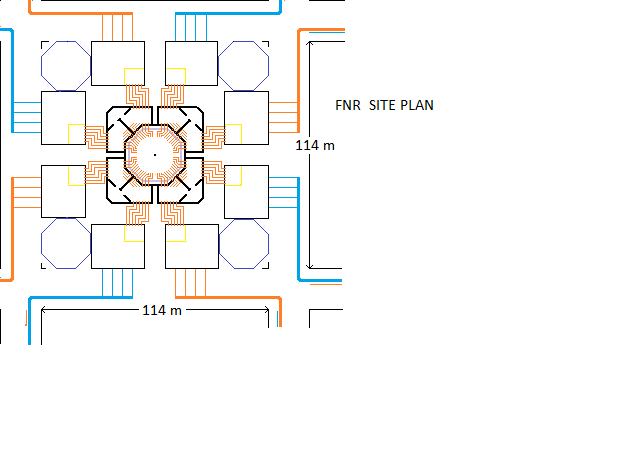
Chzrcoal = Sodium Pool Wall
Grey = concrete inner and outer structural walls, shear walls
Black = turogenerator barn outline
Pink = argon silos
Blue = Cooling Tower
Red = boundary for above grae structures
Black corner marker = NPP property boundary
The supporting mechanical and electrical equipment is assembled from factory fabricated and tested portable modules that can be delivered by a road truck.
Nuclear temperature maintenance of the liquid sodium pool is passive, autonomous and extremely dependable. The power plant's modular mechanical/electrical equipment design permits thermal and electrical power production at reduced levels while non-nuclear mechanical and/or electrical maintenance is underway. Total power plant shutdowns of about one month duration are recommended at 6 year intervals to permit nuclear fuel bundle rearrangement and intermediate heat exchange bundle service.
An important NaK fire suppression feature is gravity drain down to a dedicated below grade dump tank for each heat transport circuit.
WORK BY OTHERS:
An early FNR was the Sodium Reactor Experiment.
This experiment suffered fuel tube failures due to:
a) Lack of sufficient gap between the fuel rods and the inside fuel tube wall to permit normal fuel swelling caused by fission product gas bubble formation;
b) Lack of sodium inside the fuel tube to efficiently transfer heat from the fuel rods to the fuel tube wall;
c) Lack of plenum space inside the fuel tubes for safe storage of compressed inert fission product gases;
d) Too thick a core zone for reactor power stability.
A later reactor was the EBR-2 which operated successfully for 30 years and was only taken out of service due to lack of continuing funding. The EBR-2 fuel design addressed all of the aforementioned fuel tube failure issues.
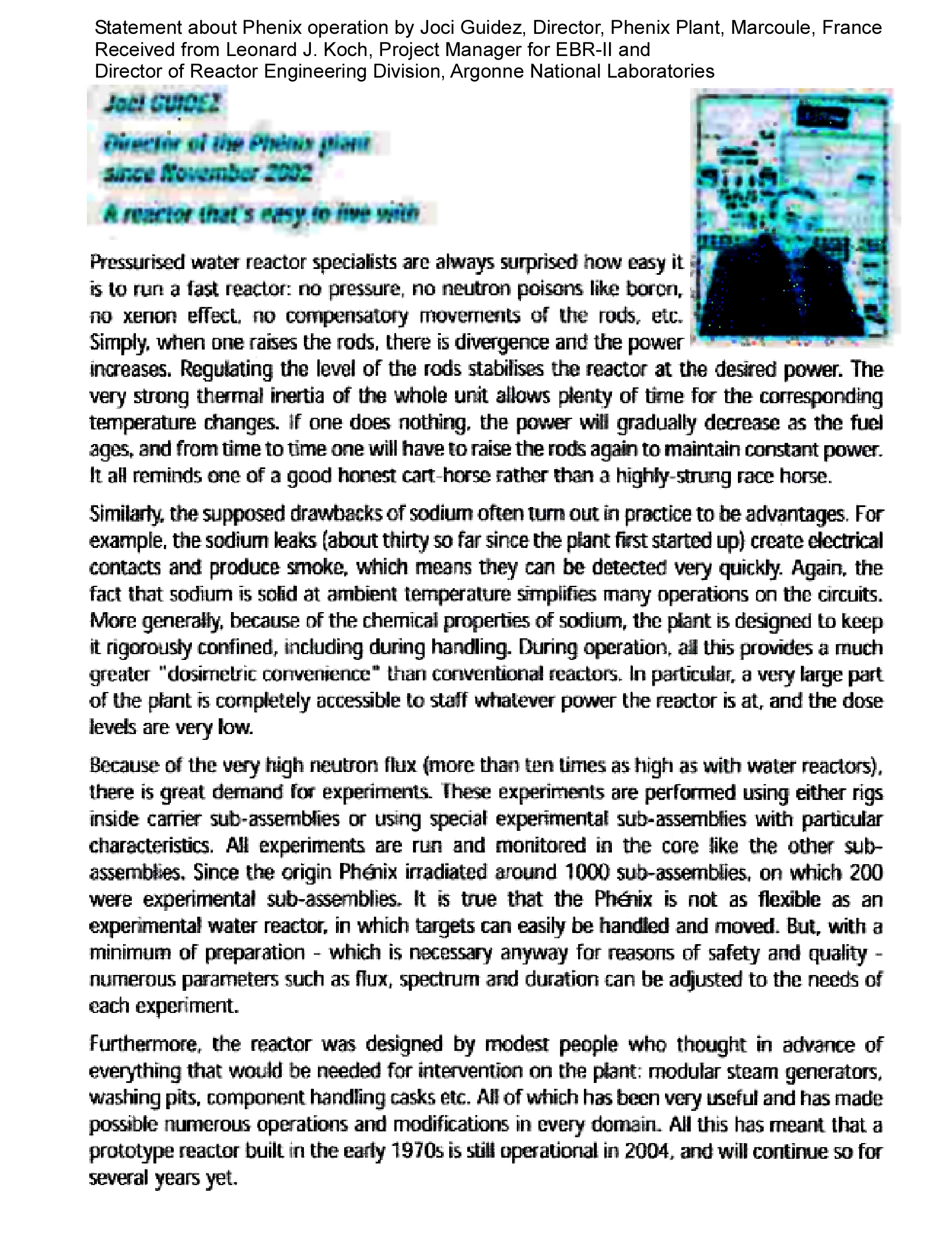
A later large sodium cooled reactor was the French:
Phenix
Phenix Guidez Statement.
A even larger sodium cooled reactor was the French:
Super Phenix
which once fully operational was closed for irrational political reasons.
A still later "paper FNR design" was the GEH PRISM (300 MWe). This reactor design was outlined in the papers: S-PRISM specs and TRIPLETT LOEWEN DOOIES-2012-PRISM. This "paper FNR" may have potential maintenance and power instability issues.
A still later "paper FNR design" is the proposed ARC-100 (100 MWe) from ARC Energy. Known fundamental problems with this "paper reactor" are lack of capacity and lack of fuel sustainability. The power stability, maintainability and waste disposal issues are not known to this author.
Another "paper FNR" is the Moltex SSR . The Moltex concept is to use molten salt fuel in fuel tubes and a different molten salt coolant instead of sodium. There are many related material challenges.
Major real Russian liquid sodium cooled power reactors include the
BN-600 (600 MWe) which has operated for over 30 years,
BN-800 (800 MWe) which has operated since late 2015
and
BN-1200 (1200 MWe) which is in developmental design review.
Today in 2021 the Chinese are building two CFR-600 (600 Mwe) sodium cooled power reactors in Xiapu County, Fujian province with the objective of operating with metallic fuel.
FNR MOTIVATION:
1) Until the US population realizes that climate change is a much bigger threat than communism, there is little prospect of sufficient new reactor funding.
2) An issue that the public fails to understand is that climate change cannot be brought under control until mankind is willing to build about 1000 X 1 GWt reactors per year for almost 50 years. In the USA that means a reactor construction funding commitment comparable to the present US defense budget.
3) An issue that US and other governments must address is that investment in new fuel sustainable nuclear reactor capacity must make economic sense for the investors. Bill Gates and Warren Buffet are presently financially backing the Natrium sodium cooled reactor. If they are not permitted to make a decent profit with Natrium reactors, other investors likely will not emulate them.
4) If the Natrium reactor is not permitted to operate with a sustainable fuel cycle, other US reactors likely also will not support a sustainable fuel cycle. This lack of energy sustainability issue is as much a danger to the survival of mankind as is the present CO2 driven climate change.
FNR DEPLOYMENT PROGRESS:
As of 2021 the Russians and Chinese are far ahead of North America in terms of fast neutron reactor development and deployment. However, in August 2020 a new North American team known as Natrium, which includes TerraPower (Bill Gates), Warren Buffett and GE Hitachi, formed to seriously compete in the North American electricity market. This team contemplates use of a pool type sodium cooled reactor with a sodium secondary heat transport loop and a molten nitrate salt tertiary heat transport loop. At this time the Natrium business plan is more concerned with capital cost reduction and US regulatory compliance than with fuel sustainability and nuclear waste reduction.
Natrium plans on providing some molten salt thermal energy storage with each reactor. The following video outlines the Natrium Plan. A June 17, 2021 news story summarizes a critical view of the Natrium plan.
INDIAN FNR:
A modern FNR design that is currently being promoted in India is described in the paper titled: Physics Design of Experimental Indian LMFBRs.
*******************************************************************
There is a gadolinium skirt and a 1.9 m wide liquid sodium guard band surrounding the entire fuel assembly that absorbs any neutrons that escape from the fuel assembly to prevent these escaping neutrons causing cumulative neutron excitation and long term physical damage to the sodium pool structure and to the intermediate heat exchange bundles that are immersed in the liquid sodium adjacent to the pool side walls.
The fissile atom Pu-239 has the property that if it captures a free neutron it usually fissions and emits an average of 3.1 free neutrons per fission. Each fission reaction also emits about 200 MeV of heat energy.
If the FNR core zone is too thin or the fissile atom concentration in the core zone is too low the probability of a neutron that is emitted by one fissile atom being captured by another fissile atom before that neutron is absorbed by a non-fissile atom is less than (1 / 3.1), so no chain reaction is possible and the free neutron concentration in the core zone and the rate of fission heat production remain close to zero. However, if the core zone thickness is slowly increased while the fissile atom concentration in the core is sufficiently large the probability of a neutron emitted by one fissile atom being captured by another fissile atom eventually reaches (1 / 3.1). At this point a nuclear chain reaction commences and the concentration of free neutrons and the consequent rate of heat production in the core fuel both rapidly rise.
The nuclear heat production in the core zone causes the core fuel temperature to rise which, via thermal expansion, increases the average interatomic distance between core fuel fissionable atoms. This thermal expansion reduces the rate at which neutrons are captured by Pu-239 atoms in the core zone and hence increases the rate at which neutrons diffuse out of the core zone into the blanket zone. The net result is that the temperature To at which the FNR reactivity is zero is fuel geometry dependent. At nuclear fuel temperatures less than To the free neutron concentration rises which produces more heat in the core zone fuel which causes a core zone temperature rise. At core zone temperatures above To the free neutron concentration in the core zone falls which stops heat production and hence stops the core zone fuel temperature rise.
Thus the average core zone fuel temperature is a function of the core zone geometry. As long as:
To > ambient temperature
as the core zone thickness increases so also does To. As the core zone thickness decreases so also does To.
As the fissile atom concentration in the core zone decreases so also does the core zone temperature. In the power FNR described herein as fissile fuel is consumed the core zone thickness must be periodically mechanically increased so that as the fissile atom concentration decreases over time the average core zone fuel temperature To remains constant.
When this fuel assembly is immersed in cool liquid sodium that liquid sodium warms, thermally expands and naturally rises through the vertical coolant channels in the fuel assembly. At its discharge from the top of the fuel assembly its average temperature is about 460 degrees C. This high temperature liquid sodium then flows radially outward across the top of the liquid sodium pool and then down through intermediate heat exchange bundles, where it cools down to about 410 degrees C, before flowing back radially toward the bottom center of the primary sodium pool. The heat removed from the flowing liquid sodium by the intermediate heat exchange bundles is transported to another building where it is used to make steam for electricity generation.
When the reactor thermal load is at its rated maximum the peak core fuel rod centerline temperature is 510 degrees C.
At full load there is an ~ 53 degree C temperature difference between the core fuel rod center line and the core fuel rod outside surface. Hence at full load the peak fuel rod surface temperature is:
510 C - 53 C = 457 C
Allowing for a 8 degrees C temperature drop across the fuel tube wall, at full load the primary liquid sodium discharge temperature is:
457 C - 8 C = 449 C.
However, due to nonuniformity is fuel rod fissile concentration and cooling channel open cross sectional area the average top of primary sodium temperature is set at about 460 degrees C.
The minimum permitted primary liquid sodium temperature at the fuel tube inlets is 410 C.
The maximum permitted primary sodium temperature rise is:
460 C - 400 C = 60 C
.
The typical full load sodium discharge temperature is:
Tpd = 460 C
OPERATION SUMMARY:
If due to nuclear heat release the temperature of the materials increases, thermal expansion of the materials in three dimensions increases the fraction of fission neutrons diffusing from the core zone into the blanket zone and decreases the rate at which Pu atoms in the core zone capture neutrons and then fission. Hence the free neutron concentration in the core falls and the nuclear chain reaction stops. Similarly, if the core temperature decreases the chain reaction restarts. By this mechanism the FNR maintains a nearly constant average fuel temperature in the core zone.
FNR SODIUM POOL THERMAL TRANSITION TIME:
At full reactor power the primary liquid sodium pool is typically at 458 degrees C in the top 6 m of sodium, where there is thermal stratification and at 400 degrees C below that. As the reactor is unloaded the elevation at which this temperature transition occurs sinks by about 3.8 m. Hence, during a switch from reactor at zero power to reactor at maximum power the liquid sodium temperature transition level rises by about 3.8 m.
If the chain reaction is initially off due to a high sodium pool temperature the amount of heat that must be extracted from the liquid sodium to bring the reactor to full power is:
3.8 m X Pi (10 m)^2 X 927 kg / m^3 X 50 deg C X 1.27 KJ / kg-deg C X 1 KWt-s / kJ
= 70,272,746 KWt-s
= 70,272 MWt-s
Assume that the power transition is caused by a 1000 MWt load step. Then the time for the FNR to fully change state in response to this load step is:
70,272 MWt-s / 1000 MWt
= 70.3 seconds
23
CORE ZONE THICKNESS ADJUSTMENT:
The reactor normally operates with a fixed insertion setting for each moveable fuel bundle. In the core zone the rate of loss of Pu by fissioning is partially offset by the rate of production of Pu via neutron capture by U-238. Reactor criticality at the desired operating temperature is maintained through the operating life of fuel bundles via periodic small incremental changes in core zone thickness. These core zone geometry changes are accomplished by using liquid sodium hydraulic actuators to slightly change the vertical overlap between movable fuel bundles and the corresponding adjacent fixed fuel bundles.
PLUTONIUM HARVESTING:
During normal FNR operation most of the surplus neutrons are absorbed by U-238 isotope atoms which naturally transmute into Pu-239 isotope and Pu-240 isotope atoms. After a reactor fuel change the removed core and blanket fuel rods should be reprocessed to extract the plutonium atoms, which should then be used to make new core fuel rods. The Pu-240 isotope formation slightly reduces the Pu-239 isotope output but has the benefit that it makes the reactor generated plutonium unsuitable for military use.
This web page last updated February 5, 2026