| Home | Energy Physics | Nuclear Power | Electricity | Climate Change | Lighting Control | Contacts | Links |
|---|
INTRODUCTION:
Elsewhere on this website sodium cooled Fast Neutron Reactors (FNRs) have been identified as the primary source of sustainable and dependable power for meeting mankind's future energy needs. This web page focuses on the design of the FNR's sodium pool. Important functions of this pool are to provide physical protection for the fuel assembly, to retain heat, to retain sodium and to ensure exclusion of water.
ORDER OF CONSTRUCTION:
1) Dig the hole;
2) Form the baseplate;
3) Form the inner and outer structural walls up to grade level;
4) Place the support I beams;
5) Assemble the outer steel cup;
6) Leak check and fix
7) Place fire brick;
8)Assemble the middle steel cup;
9) Leak check and fix;
10) Place firebrick;
11)Assemble the inner steel cup
12)Leak check and fix;
13)Place bottom leveling plates;
14) Place positioning plates
15) Assemble the hot wall framing,
16) Assemble the gantry crane on the hot wall framing;
17) Use the gantry crane to assist in further construction;
18) Raise the inner structural wall;
SODIUM POOL MAJOR DIMENSIONS:
The inside diameter of the sodium pool should be 20.0 m to allow for a 11.4 m nominal diameter reactor core, a 1.20 m wide perimeter reactor blanket, a 0.60 m wide ring for storing used active fuel bundles, a circular 1.8 m wide fuel bundle movement path and a 1.7 m wide perimeter ring for intermediate heat exchange bundles. The sodium depth must be 15 m to allow 6 m high intermediate heat exchanger tubes, 6 m high fuel tubes and a 3 m guard band thickness underneath the fuel tubes.
The bottom 3 m of the liquid sodium is divided into a 1.5 m height for movable fuel bundle supports and 3 m for fixed fuel umdle supports. In both cases the fuel bundle probe penetrates 1.1 m into its support pipe.
There are no penetrations of the liquid sodium pool walls or floor below the pool deck, which is 1 m above the normal sodium surface. The open steel lattice, the reactor fuel assembly and the intermediate heat exchange bundles are all inserted into the liquid sodium pool via the top surface of the sodium pool.
The top surface of the liquid sodium in the pool is nominally 1 m above grade level and 1 m below the pool deck.
Once assembled the sodium pool is permanent. There is no provision to replace the sodium pool at any time during the reactor working life. Should it need repair it can be field patched. The sodium pool walls and floor are protected by sufficient guardband thicknesses of sodium (and gadolinium) that their cumulative neutron exposure should be negligible. However, the inner steel cup is subject to continuous exposure to 400 to 500 degree C sodium.
SODIUM POOL GENERAL DESCRIPTION:
The sodium pool consists of three nested steel cups separated from each other by 1 m thicknesses of fire brick with a fill factor of at least 50%.
The fire brick must incorporate sufficient thermal insulation that under normal circumstances heat loss out the sides and bottom of the sodium pool is minimal. There must be a gap on the inner side of the firebrick filled with compressible glass wool insulation to allow differential thermal expansion.
SODIUM POOL DIMENSIONS:
The innermost nested steel cup is 20 m inside diameter X 16 m deep;
The middle nested steel cup is 22 m inside diameter X 16 m deep;
The outermost nested steel cup is 24 m inside diameter X 16 m deep;
KEY SODIUM POOL FEATURES:
a) The sodium pool must reliably and permanently contain the liquid sodium at 100 deg C to 500 degrees C under a variety of adverse conditions;
b) The sodium pool must reliably transfer heat to immersed heat exchange bundles;
c) The sodium pool must reliably exclude water.
d) The sodium pool elevation must allow for an unplanned rise in the surrounding water table and must tolerate limited unplanned grade level flooding.
e) The elevation of the sodium pool deck is nominally 2 m above grade and 19 m above the baseplate top surface.
f) The liquid sodium pool surface is 1 m below the pool deck.
g) There should be a 3 m wide neutron absorbing sodium guard band between the outside of the FNR fuel assembly and the sodium pool's bottom and side walls;
i) For sodium containment certainty the sodium pool consists of three nested steel cups, each of which can by itself reliably contain the sodium;
j) Each cup is cylindrical. The outer cup is 24 m dia X 16 m high. The middle cup is 22 m dia X 16 m high. The inner cup is 20 m dia X 16 m high.
k) Between the innermost cup and the middle cup is a 1 m thickness of fire brick between the bottoms and on the sides;
l) Between the middle cup and the outermost cup is a 1 m thickness of fire brick between the bottoms and on the sides.
m) Immediately outside the innermost cup walls is a 2 inch thick empty space to allow for greater thermal expansion by the innermost cup than by the middle cup.
n) Immediately outside the middle cup walls is a 2 inch thick empty space to allow for greater thermal expansion by the middle cup than by the outermost cup.
o) Fire brick is used for thermal insulation between the nested cups. Fire brick should be selected to provide the required 50% fill factor. The chosen firebrick must not long term chemically interact with the sodium or steel.
p) The fill factor is important because it must be sufficient to prevent the sodium level dropping too much in the event of both innermost and middle nested steel cup leaks.
q) In the event of failures of the inner and middle nested cups the sodium top surface must not drop so far that fission product decay heat can not be readily removed via the 6 m high intermediate heat exchange bundles.
r) The innermost cup sidewall plates stabilize the horizontal position of the open steel lattice.
s) The intermediate heat exchange bundles radially slide on pool deck mounted pipe stands and move up and down to accommodate radial pipe thermal expansion and contraction.
t) The pool deck is slightly sloped toward the inner cup to provide drain back of sodium vapor condensate to the sodium pool and to guide the rolling of buoyant metal balls used for sodium fire asphixiation.
SODIUM POOL FABRICATION
a) Each nested cup consists of a butt welded flat bottom and butt welded hot bent sidewall plates that have preformed 10, 11 or 12 m radii of curature.
b) The inner and middle cup pieces are fabricated from 0.75 inch thick sheet steel. The outer cup is fabricated from 1.00 ____inch thick sheet steel.
c) The dimensions of the individual parts used to form the sodium pool must be consistent with road truck and rail transport.
d) The innermost cup should be made of 316L stainless steel to minimize long term dissolution of the innermost cup by high temperature liquid sodium and to provide for weldability.
e) All the parts of each cup should be made of the same alloy to minimize thermal stress on thermal expansion and contraction.
f) The flat bottoms of the nested steel cups are each formed from 28 pie shape flat sheet steel pieces. Each piece subtends an angle of:
360 deg / 28 = 12.85714 degrees.
g) The flat bottom radius is 2 plate thicknesses greater than the nominal inside radius of curvature.
h) At the middle of each cup bottom is a small disk that connects together the narrow ends of the pie shaped bottom plates.
i) The required pool wall plate thickness is derived from hoop stress calculations.
j) The nested cup bottoms are welded only from the top. The side walls are welded from the inside. leak tested with water and then welded from the outside. the outside weld reduces hop stress.
k) The nested cup assembly is configured for automatic butt welding, similar to that used for pipelines.
l) When each cup's welding is complete the bottom is covered with levelling strips between welds to make the bottom present a pseudo-level upper surface.
m) It must be practical to move an active fuel bundle from the reactor core to a cooling position on the fuel assembly perimeter without lifting the fuel bundle's core or blanket rods above the top surface of the liquid sodium pool. This requirement sets an overall 8 m constraint on the fuel bundles.
FIRE BRICK QUANTITIES:
w) The volume of fire brick inside the outer cup that supports the middle cup is:
Pi (12 m)^2 (1 m) = 452.4 m^3
The volume of fire brick inside the middle cup that supports the inner cup is:
Pi (11 m)^2 (1 m) = 380.1 m^3
x) The volume of fire brick between the outer cup and the middle cup is:
[Pi (12m)^2 - Pi (11 m)^2] (12 m) = 867.1 m^3 sand
On top of the fire brick is:
[Pi (12m)^2 - Pi (11 m)^2] (5 m) = 361.3 m^3 fibrefrax.
The volume of fire brick between the middle cup and the inner cup is:
[Pi (11 m)^2 - Pi (10 m)^2] (16 m) = 1005.6 m^3 sand
SODIUM POOL SUPPORT I BEAMS:
The outer cup is supported by a layer of I beams each 1 m wide X 1 m high. These I beams provide both bottom ventilation and service access. The total I beam length requirementis 24 m X 24 = 576 m. These I beams are delivered in 48 X 12 m lengths. At each end of the I beams are cooling air manifolds.
MAXIMUM SODIUM VOLUME:
The maximum sodium volume is:
Pi (10 m)^2 (15 m) = 4712.4 m^3. This volume is reduced by the volumes of the fuel assembly, open steel lattice, and intermediate heat exchange bundles.
SODIUM POOL WALL MATERIAL:
The EBR-2 sodium pool had no visible corrosion of its stainless steel alloy after 30 years of operation. The corrosion of stainless steel by liquid Na, as reported by the EBR-2 experiment, was negligibly small. The exact alloy is detailed in the attached file referred to as: EBR-II stainless steel alloy analysis.
However, we do not have good information with respect to the temperature and impurity concentration in the EBR-2. Here is a reference relevant to corrosion of various steels by caustic soda.
When air is excluded the common stainless steels 304 and 316 are believed to be long term thermally stable at 460 degrees C .
Web sites dealing with stainless steel indicate that its corrosion resistance decreases after prolonged exposure to temperatures greater than 425 degrees C. In this respect 316 SS is believed to be significantly more corrosion resistant than 304 SS. Since the sodium pool is extremely difficult to replace it should be formed from 316L SS. Note that 316L SS is slightly more expensive than 304L SS. TheLis important for weldability.
However, we do not have good information with respect to the temperature and impurity concentration in the EBR-2. Here is a reference relevant to corrosion of various steels by caustic soda.
GANTRY CRANE LIFTING REQUIREMENT:
The maximum width of an outer cup sidewall plate is:
24 m Pi / 20 = 3.7699 m.
These can be transported on their edges on a low bed flat deck truck.
The gantry crane must be able to lift the largest single sodium pool component. The outermost cup sidewall plates are 8 m X 24 Pi m/ 20. If these plates are 0.75 inch thick then each one weighs:
8 m x (24 Pi m / 20) X 0.75 inch X .0254 m / inch X 7.874 X 1000 kg / m^3
= 4294 kg
= 4.295 tonnes
Hence, the polar gantry crane must be rated for lifting at least 5 tonnes.
Each nested cup contains 60 major parts.
WELD LEAKAGE:
The reason for having three nested cups is to ensure that liquid sodium will never leak out and water will never leak in.
If water enters the space between the outer and the middle cups or if sodium enters the space between the inner and the middle cups then the reactor should be shut down for pool repair at the next opportunity.
If the innermost and middle cups both fail liquid sodium will fill the gas spaces in the immersed fire brick piles. That will cause the elevation of the liquid sodium pool surface to drop by about 4 m. Hence the bottom 2 m of the intermediate heat exchange bundles will remain immersed in liquid sodium, which is enough to remove fission product decay heat.
However, if due to a further failure of the outermost steel cup the sodium surface elevation continues to drop, that circumstance is very dangerous because:
a) As the sodium surface drops below the intermediate heat exchange bundles heat removal will stop;
b) Fission product decay heat will keep raising the temperature of the fuel and the remaining liquid sodium;
c) Eventually the high fuel temperature will cause fuel melting, which should be confined by the fuel tubes;
d) Eventually the remaining liquid sodium temperature will reach its boiling point causing high pressure sodium vapor emission;
e) If the sodium surface level drops to the level of the fissile fuel rods fuel melting can occur even if the movable fuel bundles are fully retracted.
The bottom line is that even after the movable fuel bundles are fully withdrawn from the matrix of fixed fuel bundles it is crucial to ensure that the sodium pool level is maintained and that there is always sufficient cooling by natural NaK circulation to reject remaining fission product decay heat. Hence, from a walkaway safety perspective it is essential that the sodium pool consist of three nested steel cups that are spaced such that the largest possible sodium surface elevation drop is 4 m.
CONTAINED VOLUMES:
Consider the top 4 m in the sodium pool. The associated volume is about:
4 m (Pi) (10 m)^2 = 400 Pi m^3 = 1256.6 m^3
Assume that due to a sidewall leak the sodium level drops by 4.0 m.
The fire brick volume between
the inner and middle nesting cups below the potentially lowered sodium level is:
Pi (11 m)^2(1 m) + Pi [(11 m)^2 - (10 m)^2](12 m)
= Pi[121 m^3 + 21 m^2 (12 m)]
= Pi [373 m^3]
The fire brick volume between
the middle and outer nesting cups below the potentially lowered sodium level is:
Pi (12 m)^2(1 m) + Pi [(12 m)^2 - (11 m)^2](13 m)
= Pi [144 m^3] + Pi (23 m^2) 13 m]
Assuming that the fire brick occupies 50% of the available volume
the volume of sodium that could be absorbed is:
Pi[373 m^3 + 443 m^3] / 2 = Pi[816 m^3 /2] = 1281.8 m^2.
Hence we must be certain that the fire brick fill
factor is at least 50%.
If the inner cup and the middle cup walls both fail the liquid sodium level in the inner cup will drop by slightly more than 4.0 m.
FILL FACTOR CONSTRAINT:
For comparison the fractional unfilled volume in a cubic stack of spheres is:
[8 R^3 - (4 / 3) Pi R^3] / 8 R^3 = 0.476
FUEL BUNDLE CLEARANCE ISSUES:
The fuel bundles have an overall height of 8.0 m. To relocate a fuel bundle it must be lifted about 8.0 m to clear other fuel bundles. When so lifted the top 2.1 m of the fuel bundle are above the liquid sodium surface.
There must be adequate room for liquid sodium natural circulation. At the sodium pool perimeter the available vertically flowing sodium cross sectional area is:
Pi [(10 m)^2 - (7.0 m)^2]
= 51 Pi m^2
The cross sectional area to vertical flow occupied by the intermediate heat exchange bundles is:
48 Pi (0.5 m)^2 = 12 Pi m^2
Hence the actual perimeter open area is:
51 Pi - 12 Pi = 39 Pi m^2
This vertical flow cross sectional area is required to provide the intermediate bypass circulation required to raise the return temperature from 340 C to 400 C.
At he outer perimeter of the core zone the cross sectional area to vertical flow available for sodium circulation is:
Pi (10 m)(3 m) = 30 Pi m^2
Thus when the reactor is operational the 3 m underneath the fuel assembly must be truly open to allow adequate radial sodium natural circulation.
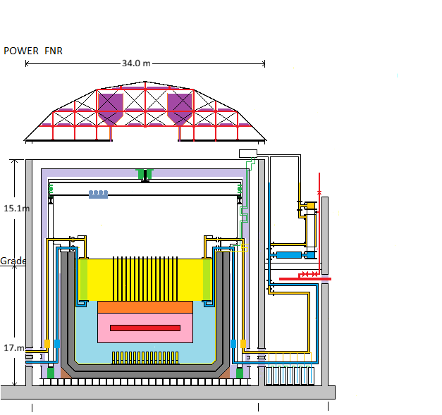
This nested cup configuration is shown on the following FNR side elevation diagram.
THERMAL CONDUCTIVITY:
The insulating brick used in this application should have low thermal conductivity. The issue of filler thermal conductivity is discussed in the Stack Thesis.
GAMMA SHIELDING:
The density of insulating brick is about 0.6 to 1.2 gm / cm^3.
On a per unit area basis the best shielding provided by insulating brick is:
200 cm X 1.2 gm / cm^3 = 240 gm / cm^2
In addition there is the weight of steel. There are 3 layers of steel, (3 X 0.75 inch thick), for a total of 2.25 inches. The density of steel is about:
7.874 gm / cm^3.
Thus the shielding provided by the steel is:
2.25 inch X 2.54 cm / inch X 7.874 gm / cm^3 = 45.0 gm / cm^2
Hence under normal circumstances the total gamma shielding provided by the sodium pool wall with dense insulating brick filler is:
240 + 45 = 285 gm / cm^2
By comparison the density of lead is 11.343 gm / cm^3. Hence 30 cm of lead provides gamma shielding of:
30 cm X 11.343 gm / cm^3 = 340.3 gm / cm^2
Hence a 2 m thickness of insulating brick plus 2.25 inch steel is a less effective gamma ray shield than a 30 cm thickness of lead.
Hence below the pool deck and inside the inner structural wall the service space is accessible when the reactor is operating if the brick has a density ~ 1.5 gm / cm^2
POOL WALL HOOP STRESS:
Consider the case of sodium in the inner pool but atmospheric pressure between the inner and middle cups.
The maximum allowable working stress for stainless steel at 500 degrees C is:
10,000 psi X 101,000 Pa / 14.7 psi = 68,707,483 Pa = 68.7 MPa
The density of the liquid sodium is about 927 kg / m^3
The acceleration of gravity is about 9.8 m / s^2
Hence the maximum static head sodium pressure at the bottom of the inner cup is given by:
15.0 m X 927 kg / m^3 X 9.8 m / s^2 = 136.27 kPa
At this point the radius of curvature is: 10 m
Let W = inner most cup wall thickness.
Then the wall hoop stress on the inner most cup wall material at the weld is:
136.27 kPa X (10 m ) / (wall thickness)
= 136.27 kPa X 10 m / (0.75 inch X 0.0254 m / inch)
= 71,532 kPa X 14.7 psi / 101 kPa
= 10,411 psi
This stress is OK because at the bottom of the side walls is stress relieved by:
the outside weld to the bottom of the cup.
.
The middle and outer cup material thickness of 0.75 inch is OK because while in each case the cup diameter is greater the potential sodium head is less..
OUTER CUP HYDRAULIC HEAD ISSUES:
The above hydraulic head calculation is only valid if the sodium between the middle and outer cups acts like a liquid,
In reality when the liquid sodium reaches the outer cup it will partially freeze, so liquid like hydraulic head calculations will no longer be valid.
THERMAL CONDUCTION:
The pool wall outside surface area is:
Pi (18 m) 2 (12 m) + Pi (12 m)^2
= Pi (12 m) (48 m)
= Pi (576 m^2)
The thermal conductivity of insulating brick is in the range:
0.2 to 0.4 W / m-deg C
The maximum heat loss via thermal conduction through the pool walls and floor is:
Pi (576 m^2) X 0.5 W / m-deg C X 505 deg C X (1 / 2 m)
= 228,456 Wt
= 228.5 kWt
which suggests that we need to aditionally thermally insulate the outside of the sodium pool.
SODIUM POOL MELTING
The FNR sodium pool needs at least 50 kW of immersion heater capacity for liquid sodium melting at startup. This heat may be applied by one or more of the NaK loops. Note that it is impossible to install, move or remove any fuel bundles or intermediate heat exchange bundles until after the liquid sodium has completely melted.
THERMAL EXPANSION:
The thermal coefficient of expansion of stainless steel is:
16 um / m deg C
Thus the radial expansion of the innermost cup in transitioning from 15 deg C to 500 deg C is:
485 deg C X 16 X 10^-6 / deg C X 10 m = 0.0824 m = 8.2 cm.
The corresponding radial expansion of the second cup will be about 4 cm.
This 4 cm of differential expansion must be absorbed by the expansion space beside the brick filler.The pool liner side walls will also vertically expand:
505 deg C X 16 X 10^-6 / deg C X 16.0 m = 0.129 m
Thus the hot pool deck must be free to move up and down with respect to adjacent cool walls.
The walls above the pool deck will vertically expand by:
505 deg C X 17 X 10^-6 / deg C X 14 m = 0.12 m
Hence the 1 m thick fiber ceramic insulation between the pool enclosure metal ceilings must compress by:
.137 m + .12 m = 0.257 m or 25.7% insulation compression.
The pool deck is rigidly welded to the inner nesting cup. Hence the fiber ceramic in the 1 m thick walls above the pool deck must accommodate pool deck radial expansion of about 9 cm or 9% insulation compression.
POOL DETAILS:
On top of the exposed brick is a sheet steel pool deck. The pool deck is welded to the inner most stainless steel nesting cup and slides over the other two stainless steel nesting cups to permit stress free thermal expansion and contraction.
On top of the inner most cup bottom is a sheet steel layer which protects the underlying stainless steel cup bottom from accidental damage.
On top of this protective sheet is the spacer sheet layer and then the 1.5 m to 2.5 m high open steel lattice which supports all the fuel bundles and contains the 340 ____actuators and related liquid sodium hydraulic pressure tubes for the movable fuel bundles.
************************At the bottom of the open steel lattice is a layer of gravel which has the secondary function of preventing bits of melted reactor fuel from forming a critical mass.
****************************Underneath the outermost nested steel cup bottom is 18 m diameter 1 m high space set by a row of steel I beams which rest on the concrete foundation and support the sodium pool and its contents. The outside 3 m of sodium pool radius need further support.
CONNECTION TO SODIUM POOL ENCLOSURE:
Below the pool deck and outside the outer cup wall is a 1.2 m wide air gap for air cooling and for maintenance access to the below pool space. Within the air gap between the outer stainless steel cup wall and the concrete wall inner face are structural steel radial elements which stabilize the outer pool wall. In the event of inner and middle nested steel cup failures this structural steel relieves hoop stress in the outer nested cup steel wall.
POOL STEEL APPROXIMATE QUANTITIES:
The area of the stainless steel sheet forming the sodium pool outer cup bottom is:
Pi (12 m)^2 = 452.4 m^2
The area of the stainless steel sheet forming the sodium pool outer cup wall is:
Pi (24 m) (18 m)
= 1357.2 m^2
Sodium pool outer cup total surface area is:
452 m^2 + 1357.2 m^2 = 1809.6 m^2
The area of the stainless steel sheet forming the sodium pool middle cup bottom is:
Pi (11 m)^2 = 380.1 m^2
The area of the stainless steel sheet forming the sodium pool middle cup wall is:
Pi (22 m) (17 m)
= 1175.0 m^2
Sodium pool middle cup stainless steel total area is:
380.1 m^2 + 1175.0 m^2 = 1555.1 m^2
The area of the stainless steel sheet covering the sodium pool inner cup bottom is:
= Pi (10 m)^2
= 314.2 m^2
The area of the stainless steel sheet covering the sodium pool inner cup walls is
Pi (20 m) (16 m)
= 1105.3 m^2
Total inner cup area is:
314.2 m^2 + 1105.3 m^2 = 1419.5 m^2
The area of stainless steel sheet metal covering the sodium pool deck is:
= Pi (12.0^2 - 10.0^2) m^2
= 138.2 m^2
The briks supporting the sodium inside cup floor must be flat because they carry the entire weight of the liquid sodium plus the weight of the fuel bundles, open steel lattice plus the weight of the sodium piping plus the weight of the fuel bundles in storage plus the weight of the pool walls and floor, including the 2 m thickness of brick insulation.
EARTHQUAKE TOLERANCE:
Consider the earthquake acceleration and displacement that are necessary to cause the liquid sodium level to rise 1 m on one side of the pool and drop 1 m on the other side of the pool. This situation corresponds to a sustained horizontal acceleration of about 0.1 g.
Note that there are no wall penetrations at wall heights normally exposed to liquid sodium. At wall heights where there are wall penetrions for pipes and air locks the exposure to hot sloshed liquid sodium is only transient and is extremely rare.
The pool gantry track, which carries the gantry crane, is not structurally intended to withstand even sloshed liquid sodium. Hence an earthquake acceleration sufficient to cause a slosh of liquid sodium higher than 6 m will almosst certainly result in a facility repair shutdown for an extended period.
SODIUM STRATIFICATION:
The thermal coefficient of expansion (TCE) of sodium is relatively large which implies that given an opportunity sodium will naturally thermally stratify. Hence when sodium is cooled by the intermediate heat exchange bundles the cool sodium tends to sink to the bottom of the sodium pool.-Hence, unless preventive measures are used, the temperature distribution in the liquid sodium will be one where the liquid sodium is coolest near the pool walls and along the pool bottom and is progressively warmer in the direction of the fuel assembly. Then the sodium that actually enters the bottom of the fuel assembly will get there via two routes. At full load about (2 / 3) of the circulating sodium flow volume will be warm ssodium because it circulates close to the fuel assembly. About (1 / 3) of the circulating sodium flow will be cold sodium because it is pushed up from the bottom of the sodium pool by cold sodium that flows down the inside of the pool walls.
For stable full power reactor operation we need the sodium temperature at the fuel assembly inlet to be constant independent of small changes in elevation of the stratification layer at the junction between the warm and cold sodium.
To achieve this objective without mechanical mixing the warm sodium must lose by thermal conduction the difference in temperature between the fuel assembly discharge and the fuel assembly inlet and the lost heat must raise the temperature of the sodium rising from the pool bottom by the difference in temperature between the fuel assembly inlet temperature and the pool bottom temperature.
The fuel assembly radius is about 7 m so its cross sectional area is about Pi (7 m)^2.
The maximum open area for sodium flow through the fuel assembly is about 52 m^2. About (2 / 3) of this flow becomes warm sodium and about (1 / 3) of this flow becomes cold sodium. Hence the maximum outside radius Rw of the flowing warm sodium is given by:
Pi(Rw)^2 - Pi (7 m)^2 = (2 / 3) 52 m^2
or
Rw^2 = [(2 / 3)52 m^2 + Pi (7 m)^2] / Pi
or
Rw = [(52 m^2 / Pi)(2 / 3) + (7 m)^2]^0.5
= [11.0347 m^2 + 49 m^2]^0.5
= 7.7482 m
which gives the radial width of the flowing warm sodium layer as:
Rw - 7 m = 0.7482 m
Outside the flowing warm sodium is cold sodium. To a first approximation the relevant cold sodium thickness is half of the warm sodium layer thickness or (.7482 m / 2) = .3741 m.
At the start of the circulating sodium flow path the difference in temperature between the warm sodium and the cold sodium is about 120 degrees C. Thermal conduction of heat will make this temperature difference diminish with time and flow distance.
The average thermal gradient is about:
[120 deg C / 0.5 m].
The area over which this thermal gradiant acts is about:
(2 Pi Rw)(6 m) + Pi(Rw)^2
= Pi Rw [12 m + Rw]
= Pi (7.7482 m)[12 m + 7.7482 m]
= 480.705 m^2
The thermal conductivity of liquid sodium is:
72.1 W / m-deg C
Hence the thermal power transferred by thermal conduction from the flowing warm sodium to the cold sodium is about:
[72.1 W / m deg C] X [120 deg C] X [480.705 m^2] X [1 / 0.5 m]
= 8.318 MWt
This calculated heat flow is two orders of magnitude too small. To fix this problem it is necessary to change the sodium flow pattern so that all the circulating sodium flows mixes underneath the fuel bundles.
This change will entail increasing the NaK flow through the intermediate heat exchange bundles so that the bundle temperature differential is less. ie Shunt part of the bundle discharge flow back to the bundle inlet to reduce the average bundle temperature diferential.
This issue also complicates the natural NaK flow when the induction pumps are not working.
This web page last updated March 14, 2026.
| Home | Energy Physics | Nuclear Power | Electricity | Climate Change | Lighting Control | Contacts | Links |
|---|